C O N T R O L S A N D C O N N E C T I O N S
3. MASTER SECTION | (15) |
|
(16)
(18)
(14)(17)
a. AUX Send/Return Function and Operation
(18) AUX RETURN
(29) AUX RETURN CONTROL
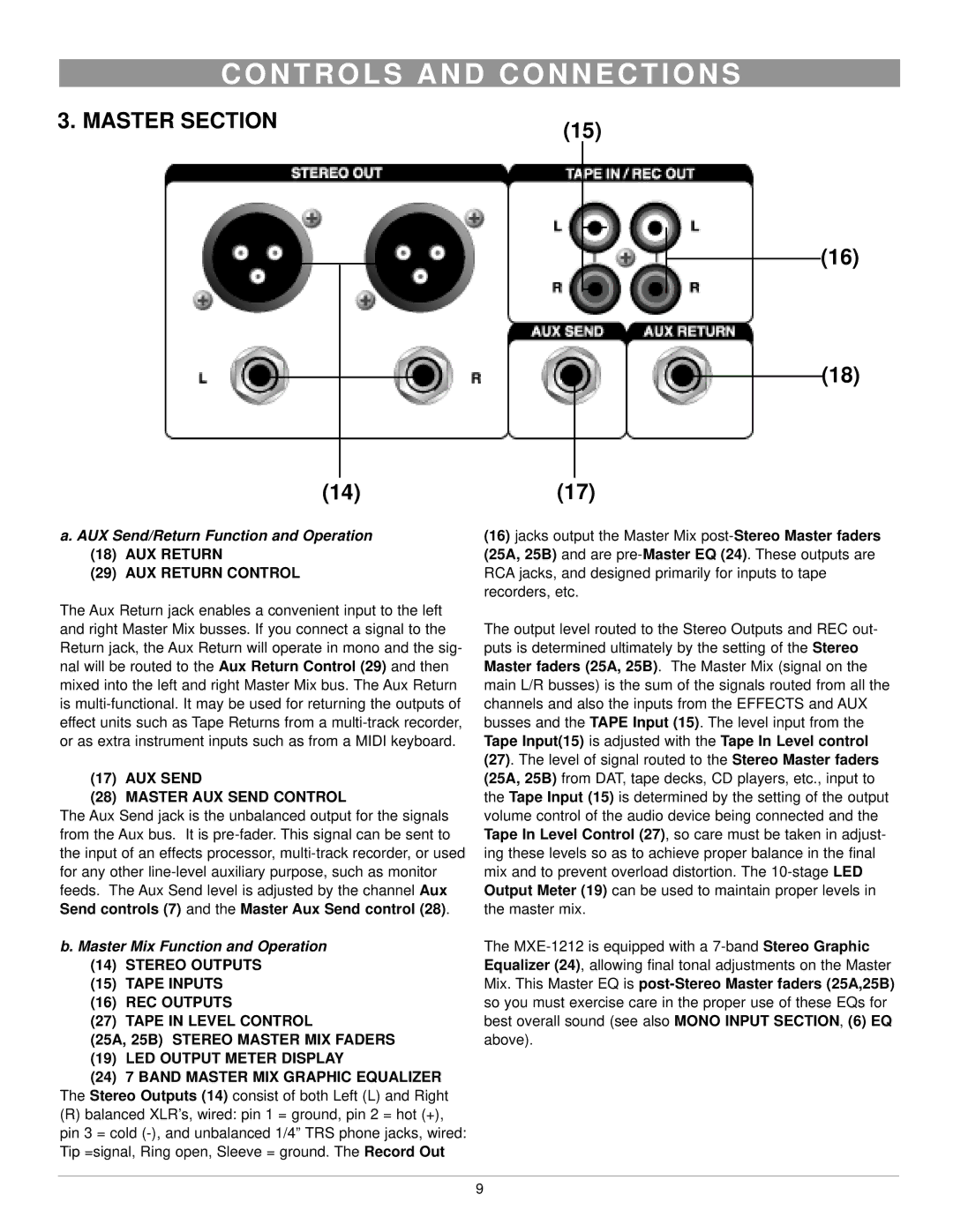
The Aux Return jack enables a convenient input to the left and right Master Mix busses. If you connect a signal to the Return jack, the Aux Return will operate in mono and the sig- nal will be routed to the Aux Return Control (29) and then mixed into the left and right Master Mix bus. The Aux Return is
(17) AUX SEND
(28) MASTER AUX SEND CONTROL
The Aux Send jack is the unbalanced output for the signals from the Aux bus. It is
b. Master Mix Function and Operation
(14)STEREO OUTPUTS
(15)TAPE INPUTS
(16)REC OUTPUTS
(27) TAPE IN LEVEL CONTROL
(25A, 25B) STEREO MASTER MIX FADERS (19) LED OUTPUT METER DISPLAY
(24)7 BAND MASTER MIX GRAPHIC EQUALIZER The Stereo Outputs (14) consist of both Left (L) and Right
(R)balanced XLR’s, wired: pin 1 = ground, pin 2 = hot (+), pin 3 = cold
(16)jacks output the Master Mix
The output level routed to the Stereo Outputs and REC out- puts is determined ultimately by the setting of the Stereo Master faders (25A, 25B). The Master Mix (signal on the main L/R busses) is the sum of the signals routed from all the channels and also the inputs from the EFFECTS and AUX busses and the TAPE Input (15). The level input from the Tape Input(15) is adjusted with the Tape In Level control (27). The level of signal routed to the Stereo Master faders (25A, 25B) from DAT, tape decks, CD players, etc., input to the Tape Input (15) is determined by the setting of the output volume control of the audio device being connected and the Tape In Level Control (27), so care must be taken in adjust- ing these levels so as to achieve proper balance in the final mix and to prevent overload distortion. The
The
9
