13
VERTICAL TERMINATION
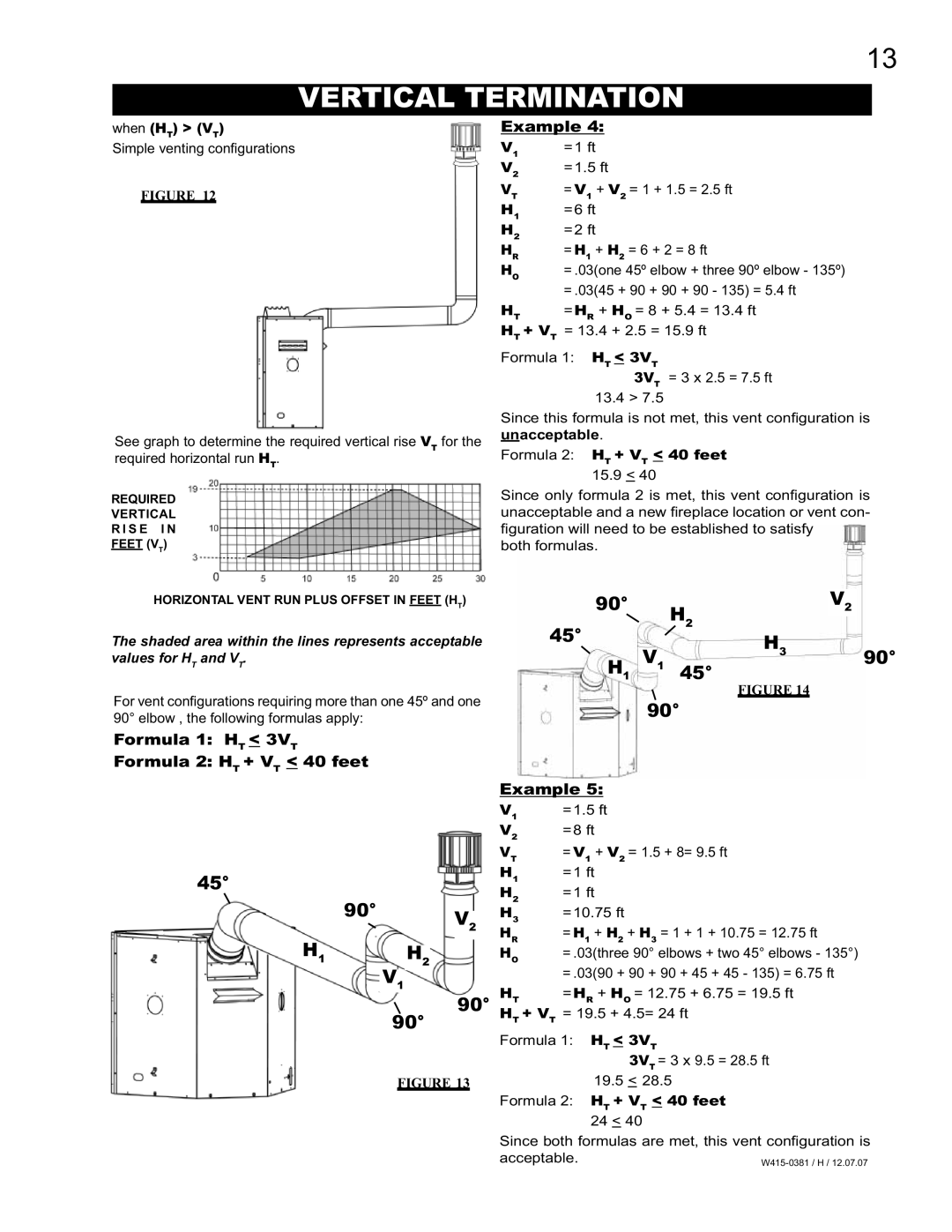
when (HT) > (VT)
Simple venting confi gurations
FIGURE 12
See graph to determine the required vertical rise VT for the required horizontal run HT.
REQUIRED
VERTICAL
R I S E I N
FEET (VT)
Example 4:
V1 | =1 ft |
V2 | =1.5 ft |
VT | = V1 + V2 = 1 + 1.5 = 2.5 ft |
H1 | =6 ft |
H2 | =2 ft |
HR | = H1 + H2 = 6 + 2 = 8 ft |
HO | = .03(one 45º elbow + three 90º elbow - 135º) |
| = .03(45 + 90 + 90 + 90 - 135) = 5.4 ft |
HT | =HR + HO = 8 + 5.4 = 13.4 ft |
HT + VT | = 13.4 + 2.5 = 15.9 ft |
Formula 1: HT < 3VT
3VT = 3 x 2.5 = 7.5 ft
13.4 > 7.5
Since this formula is not met, this vent configuration is unacceptable.
Formula 2: HT + VT < 40 feet 15.9 < 40
Since only formula 2 is met, this vent configuration is unacceptable and a new fi replace location or vent con-
figuration will need to be established to satisfy both formulas.
HORIZONTAL VENT RUN PLUS OFFSET IN FEET (HT)
The shaded area within the lines represents acceptable values for HT and VT.
For vent confi gurations requiring more than one 45º and one 90° elbow , the following formulas apply:
Formula 1: HT < 3VT
Formula 2: HT + VT < 40 feet
90° |
| H2 |
| V2 |
|
45° |
| H3 |
|
| |
|
|
|
| ||
|
|
|
|
| |
H1 | V1 | 45° | 90° | ||
|
|
|
| ||
FIGURE 14
90°
45°
90° V2
H1H2
V1
![]() 90° 90°
90° 90°
FIGURE 13
Example 5:
V1 | =1.5 ft |
V2 | =8 ft |
VT | = V1 + V2 = 1.5 + 8= 9.5 ft |
H1 | =1 ft |
H2 | =1 ft |
H3 | =10.75 ft |
HR | = H1 + H2 + H3 = 1 + 1 + 10.75 = 12.75 ft |
HO | = .03(three 90° elbows + two 45° elbows - 135°) |
| = .03(90 + 90 + 90 + 45 + 45 - 135) = 6.75 ft |
HT | =HR + HO = 12.75 + 6.75 = 19.5 ft |
HT + VT = 19.5 + 4.5= 24 ft
Formula 1: HT < 3VT
3VT = 3 x 9.5 = 28.5 ft
19.5< 28.5
Formula 2: HT + VT < 40 feet
24 < 40
Since both formulas are met, this vent configuration is acceptable.