15

USING FLEXIBLE VENT COMPONENTS

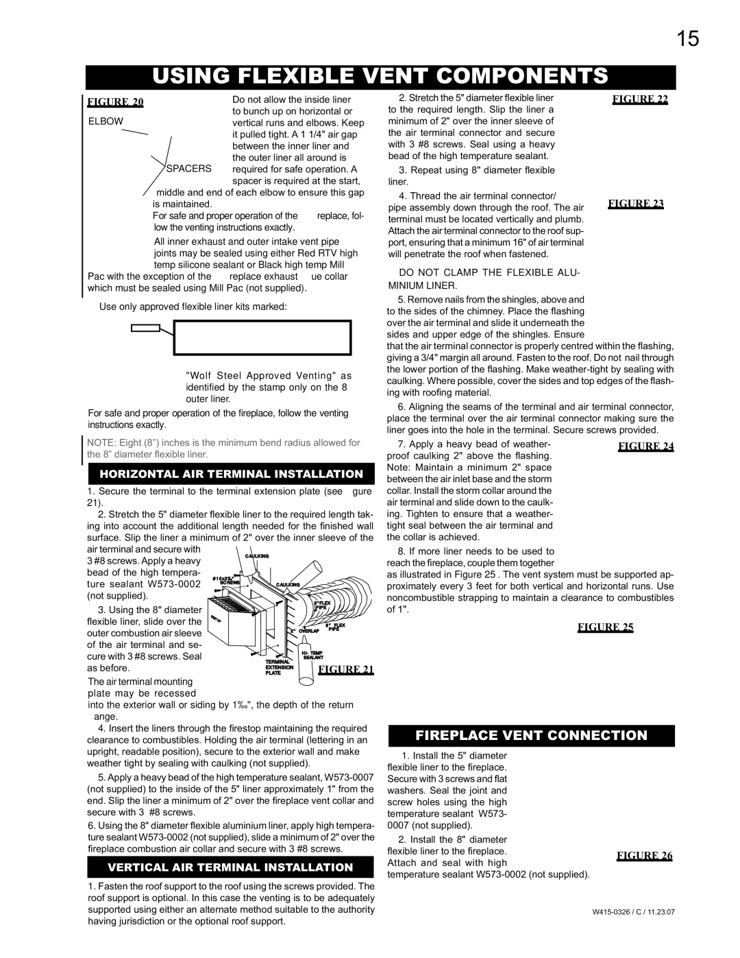
FIGURE 20

ELBOW

Do not allow the inside liner to bunch up on horizontal or vertical runs and elbows. Keep it pulled tight. A 1 1/4" air gap between the inner liner and the outer liner all around is

SPACERS required for safe operation. A spacer is required at the start, middle and end of each elbow to ensure this gap

is maintained.

For safe and proper operation of the fireplace, fol- low the venting instructions exactly.

2.Stretch the 5" diameter flexible liner to the required length. Slip the liner a minimum of 2" over the inner sleeve of the air terminal connector and secure with 3 #8 screws. Seal using a heavy bead of the high temperature sealant.

3.Repeat using 8" diameter fl exible

liner.

4.Thread the air terminal connector/

pipe assembly down through the roof. The air terminal must be located vertically and plumb. Attach the air terminal connector to the roof sup-

FIGURE 22

FIGURE 23

All inner exhaust and outer intake vent pipe joints may be sealed using either Red RTV high temp silicone sealant or Black high temp Mill

Pac with the exception of the fireplace exhaust flue collar which must be sealed using Mill Pac (not supplied).

Use only approved flexible liner kits marked:

"Wolf Steel Approved Venting" as identified by the stamp only on the 8” outer liner.

For safe and proper operation of the fireplace, follow the venting instructions exactly.

NOTE: Eight (8”) inches is the minimum bend radius allowed for the 8” diameter fl exible liner.

HORIZONTAL AIR TERMINAL INSTALLATION

1.Secure the terminal to the terminal extension plate (see figure

21).

2.Stretch the 5" diameter fl exible liner to the required length tak- ing into account the additional length needed for the fi nished wall surface. Slip the liner a minimum of 2" over the inner sleeve of the

air terminal and secure with

3 #8 screws. Apply a heavy


CAULKING


bead of the high tempera-

#10x2½"


ture sealant W573-0002


SCREWS

CAULKING


(not supplied).


5"FLEX

3. Using the 8" diameter


PIPE


fl exible liner, slide over the


8" FLEX

outer combustion air sleeve


2"

OVERLAP

PIPE


of the air terminal and se-


cure with 3 #8 screws. Seal


HI-TEMP


TERMINAL

SEALANT


as before.


FIGURE 21


EXTENSION


PLATE

The air terminal mounting plate may be recessed

into the exterior wall or siding by 1½", the depth of the return flange.

4.Insert the liners through the fi restop maintaining the required clearance to combustibles. Holding the air terminal (lettering in an upright, readable position), secure to the exterior wall and make weather tight by sealing with caulking (not supplied).

5.Apply a heavy bead of the high temperature sealant, W573-0007 (not supplied) to the inside of the 5" liner approximately 1" from the end. Slip the liner a minimum of 2" over the fi replace vent collar and secure with 3 #8 screws.

6.Using the 8" diameter fl exible aluminium liner, apply high tempera- ture sealant W573-0002 (not supplied), slide a minimum of 2" over the fi replace combustion air collar and secure with 3 #8 screws.

VERTICAL AIR TERMINAL INSTALLATION

1.Fasten the roof support to the roof using the screws provided. The roof support is optional. In this case the venting is to be adequately supported using either an alternate method suitable to the authority having jurisdiction or the optional roof support.

port, ensuring that a minimum 16" of air terminal will penetrate the roof when fastened.

DO NOT CLAMP THE FLEXIBLE ALU-

MINIUM LINER.

5.Remove nails from the shingles, above and to the sides of the chimney. Place the fl ashing over the air terminal and slide it underneath the sides and upper edge of the shingles. Ensure

that the air terminal connector is properly centred within the fl ashing, giving a 3/4" margin all around. Fasten to the roof. Do not nail through the lower portion of the fl ashing. Make weather-tight by sealing with caulking. Where possible, cover the sides and top edges of the flash- ing with roofi ng material.

6.Aligning the seams of the terminal and air terminal connector, place the terminal over the air terminal connector making sure the liner goes into the hole in the terminal. Secure screws provided.

7. Apply a heavy bead of weather-

FIGURE 24

proof caulking 2" above the fl ashing.


Note: Maintain a minimum 2" space


between the air inlet base and the storm


collar. Install the storm collar around the


air terminal and slide down to the caulk-


ing. Tighten to ensure that a weather-


tight seal between the air terminal and


the collar is achieved.


8.If more liner needs to be used to reach the fireplace, couple them together

as illustrated in Figure 25. The vent system must be supported ap- proximately every 3 feet for both vertical and horizontal runs. Use noncombustible strapping to maintain a clearance to combustibles of 1".

FIGURE 25

FIREPLACE VENT CONNECTION

1. Install the 5" diameter


fl exible liner to the fi replace.


Secure with 3 screws and flat


washers. Seal the joint and


screw holes using the high


temperature sealant W573-


0007 (not supplied).


2. Install the 8" diameter


fl exible liner to the fi replace.

FIGURE 26

Attach and seal with high


temperature sealant W573-0002 (not supplied).


W415-0326 / C / 11.23.07

Page 15
Image 15
Napoleon Fireplaces BGD48P, BGD48N manual Using Flexible Vent Components, Fireplace Vent Connection

BGD48N, BGD48P specifications

Napoleon Fireplaces has long been a name synonymous with quality and innovation, and their BGD48N and BGD48P models are prime examples of their commitment to excellence. These fireplaces serve as a beautiful focal point in any home while providing efficient heating solutions.

The BGD48N features a classic design that echoes the elegance of traditional fireplaces. With its wide viewing area, it delivers an impressive display of flames, creating a warm and inviting atmosphere. The BGD48P, on the other hand, offers a more contemporary aesthetic, featuring clean lines and a sleek facade that complements modern decor. Both models are built with high-quality materials and craftsmanship, ensuring durability and longevity.

One of the key technologies integrated into these fireplaces is the advanced heat management system, which efficiently distributes warmth throughout the room without overheating the unit. This system uses a combination of convection and radiant heat, ensuring that the space is evenly warmed while maximizing fuel efficiency. The incorporation of a ceramic glass front allows for optimal heat retention and provides an unobstructed view of the flickering flames.

The BGD48N and BGD48P are powered by Napoleon's innovative firebox technology, which permits a variety of fuel options, including natural gas and propane. This flexibility allows homeowners to choose the heating source that best fits their needs and preferences. Additionally, these models are equipped with a powerful fan system that enhances heat circulation, thereby increasing overall efficiency.

Safety and convenience are paramount in the design of these fireplaces. Each model comes with a straightforward control panel, allowing users to easily adjust the temperature and flame height. An automatic shut-off feature ensures peace of mind, providing an added layer of safety for families. The inclusion of easy-access maintenance features also makes cleaning and upkeep a breeze.

With their combination of classic styling, modern technology, and user-friendly features, Napoleon Fireplaces BGD48N and BGD48P models stand out in the market. They offer a sophisticated heating solution that not only enhances ambiance but also improves energy efficiency. Whether you are seeking a traditional touch or a modern aesthetic, these fireplaces cater to diverse tastes, making them an excellent investment for any homeowner looking to elevate their living space.