6
H E I G H T
LENGTH
ROOM 1
H
T
D
I
W
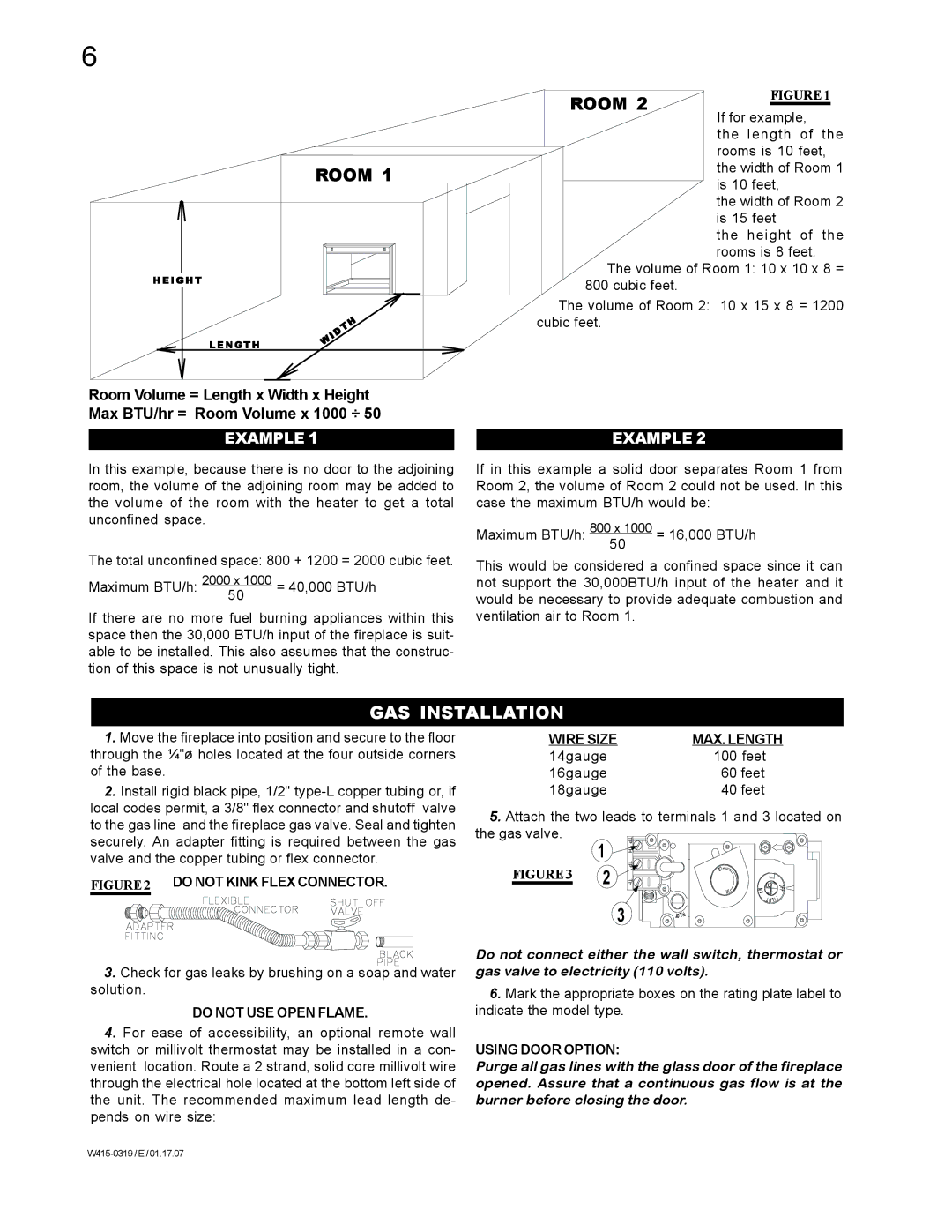
FIGURE 1
If for example,
the length of the rooms is 10 feet, the width of Room 1 is 10 feet,
the width of Room 2 is 15 feet
the height of the rooms is 8 feet.
The volume of Room 1: 10 x 10 x 8 = 800 cubic feet.
The volume of Room 2: 10 x 15 x 8 = 1200 cubic feet.
Room Volume = Length x Width x Height Max BTU/hr = Room Volume x 1000 ÷ 50
EXAMPLE 1
In this example, because there is no door to the adjoining room, the volume of the adjoining room may be added to the volume of the room with the heater to get a total unconfined space.
The total unconfined space: 800 + 1200 = 2000 cubic feet.
Maximum BTU/h: 2000 x 1000 = 40,000 BTU/h 50
If there are no more fuel burning appliances within this space then the 30,000 BTU/h input of the fireplace is suit- able to be installed. This also assumes that the construc- tion of this space is not unusually tight.
EXAMPLE 2
If in this example a solid door separates Room 1 from Room 2, the volume of Room 2 could not be used. In this case the maximum BTU/h would be:
Maximum BTU/h: 800 x 1000 = 16,000 BTU/h
50
This would be considered a confined space since it can not support the 30,000BTU/h input of the heater and it would be necessary to provide adequate combustion and ventilation air to Room 1.
GAS INSTALLATION
1.Move the fireplace into position and secure to the floor through the ¼"ø holes located at the four outside corners of the base.
2.Install rigid black pipe, 1/2"
FIGURE 2 DO NOT KINK FLEX CONNECTOR.
3.Check for gas leaks by brushing on a soap and water solution.
DO NOT USE OPEN FLAME.
4.For ease of accessibility, an optional remote wall switch or millivolt thermostat may be installed in a con- venient location. Route a 2 strand, solid core millivolt wire through the electrical hole located at the bottom left side of the unit. The recommended maximum lead length de- pends on wire size:
WIRE SIZE | MAX. LENGTH |
14gauge | 100 feet |
16gauge | 60 feet |
18gauge | 40 feet |
5. Attach the two leads to terminals 1 and 3 located on the gas valve.
| 1 |
|
|
|
|
FIGURE 3 | 2 |
| OL | O | F |
|
|
|
| ||
|
|
|
| N | O |
|
|
| HI | F | |
|
|
|
| IP | |
|
|
|
|
| |
|
| 3 |
|
| TOL |
|
| P |
|
| |
|
|
| TOLI |
|
|
Do not connect either the wall switch, thermostat or gas valve to electricity (110 volts).
6.Mark the appropriate boxes on the rating plate label to indicate the model type.
USING DOOR OPTION:
Purge all gas lines with the glass door of the fireplace opened. Assure that a continuous gas flow is at the burner before closing the door.