CONFIDENTIAL
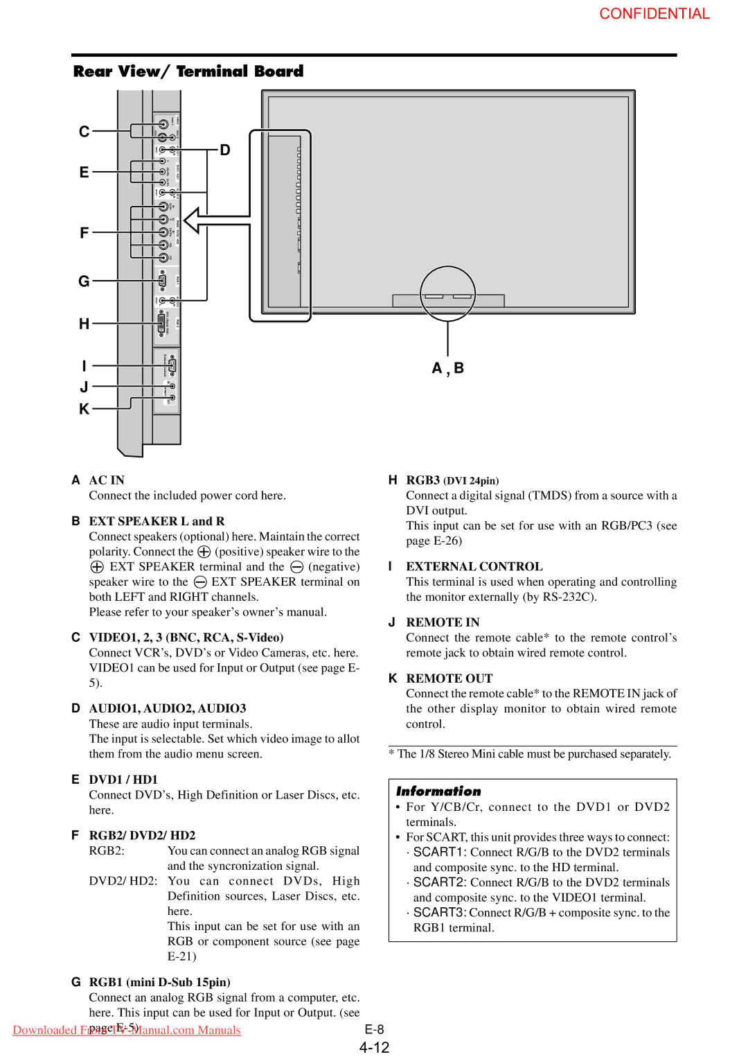
Rear View/ Terminal Board
C
E
F
G
H
I
J
K
|
| VIDEO 1 | VIDEO |
VIDEO 3 |
|
| VIDEO 2 |
( |
|
| AUDIO 1 |
MONO |
|
| |
) | L | R | |
| Y |
|
|
| Cb/Pb Cr/Pr |
| DVD1 / HD1 |
( |
|
| AUDIO 2 |
MONO |
|
| |
) | L | R | |
| Cr/Pr | R/ |
|
| G/ Y | RGB2 | |
| Cb/Pb | B/ | / DVD2 |
| HD |
| / HD2 |
| VD |
|
|
|
|
| RGB 1 |
( |
|
| AUDIO 3 |
MONO |
|
| |
) | L | R | |
| DV I |
|
|
| ( |
| RGB 3 |
| Digital |
| |
| RGB |
|
|
| ) |
|
|
| External Control |
|
|
| I N |
|
|
| REMOTE |
|
|
| OUT |
|
|
D
A B
AAC IN
Connect the included power cord here.
BEXT SPEAKER L and R
Connect speakers (optional) here. Maintain the correct
polarity. Connect the![]() (positive) speaker wire to the
(positive) speaker wire to the ![]() EXT SPEAKER terminal and the
EXT SPEAKER terminal and the ![]() (negative)
(negative)
speaker wire to the EXT SPEAKER terminal on both LEFT and RIGHT channels.
Please refer to your speaker’s owner’s manual.
CVIDEO1, 2, 3 (BNC, RCA, S-Video)
Connect VCR’s, DVD’s or Video Cameras, etc. here. VIDEO1 can be used for Input or Output (see page E- 5).
DAUDIO1, AUDIO2, AUDIO3 These are audio input terminals.
The input is selectable. Set which video image to allot them from the audio menu screen.
EDVD1 / HD1
Connect DVD’s, High Definition or Laser Discs, etc. here.
FRGB2/ DVD2/ HD2
RGB2: | You can connect an analog RGB signal |
| and the syncronization signal. |
DVD2/ HD2: You can connect DVDs, High Definition sources, Laser Discs, etc. here.
This input can be set for use with an RGB or component source (see page
HRGB3 (DVI 24pin)
Connect a digital signal (TMDS) from a source with a DVI output.
This input can be set for use with an RGB/PC3 (see page
IEXTERNAL CONTROL
This terminal is used when operating and controlling the monitor externally (by
JREMOTE IN
Connect the remote cable* to the remote control’s remote jack to obtain wired remote control.
KREMOTE OUT
Connect the remote cable* to the REMOTE IN jack of the other display monitor to obtain wired remote control.
* The 1/8 Stereo Mini cable must be purchased separately.
Information
•For Y/CB/Cr, connect to the DVD1 or DVD2 terminals.
•For SCART, this unit provides three ways to connect: ·SCART1: Connect R/G/B to the DVD2 terminals
and composite sync. to the HD terminal. ·SCART2: Connect R/G/B to the DVD2 terminals
and composite sync. to the VIDEO1 terminal. ·SCART3: Connect R/G/B + composite sync. to the
RGB1 terminal.
GRGB1 (mini D-Sub 15pin)
Connect an analog RGB signal from a computer, etc.
here. This input can be used for Input or Output. (see
page