Connections
NOTE: Do not connect/disconnect cables when turning on the monitor or other external equipment as this may result in a loss of the monitor image.
NOTE: Use an audio cable without a
Before making connections:
*First turn off the power of all the attached equipment and make connections.
*Refer to the user manual included with each separate piece of equipment.
English
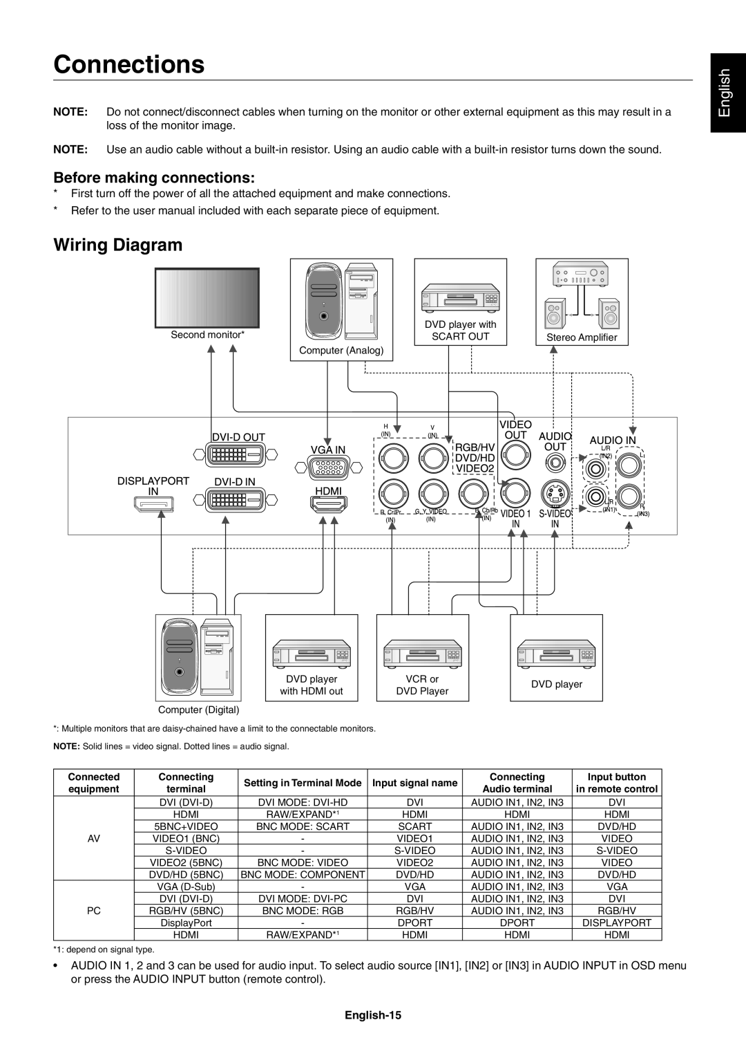
Wiring Diagram
Second monitor*
DVD player with |
SCART OUT |
Computer (Analog)
Stereo Amplifi er
DVD player | VCR or | DVD player | |
with HDMI out | DVD Player | ||
|
Computer (Digital)
*: Multiple monitors that are
NOTE: Solid lines = video signal. Dotted lines = audio signal.
Connected | Connecting | Setting in Terminal Mode | Input signal name | Connecting | Input button | |
equipment | terminal | Audio terminal | in remote control | |||
|
| |||||
| DVI | DVI MODE: | DVI | AUDIO IN1, IN2, IN3 | DVI | |
| HDMI | RAW/EXPAND*1 | HDMI | HDMI | HDMI | |
| 5BNC+VIDEO | BNC MODE: SCART | SCART | AUDIO IN1, IN2, IN3 | DVD/HD | |
AV | VIDEO1 (BNC) | - | VIDEO1 | AUDIO IN1, IN2, IN3 | VIDEO | |
| - | AUDIO IN1, IN2, IN3 | ||||
| VIDEO2 (5BNC) | BNC MODE: VIDEO | VIDEO2 | AUDIO IN1, IN2, IN3 | VIDEO | |
| DVD/HD (5BNC) | BNC MODE: COMPONENT | DVD/HD | AUDIO IN1, IN2, IN3 | DVD/HD | |
| VGA | - | VGA | AUDIO IN1, IN2, IN3 | VGA | |
| DVI | DVI MODE: | DVI | AUDIO IN1, IN2, IN3 | DVI | |
PC | RGB/HV (5BNC) | BNC MODE: RGB | RGB/HV | AUDIO IN1, IN2, IN3 | RGB/HV | |
| DisplayPort | - | DPORT | DPORT | DISPLAYPORT | |
| HDMI | RAW/EXPAND*1 | HDMI | HDMI | HDMI |
*1: depend on signal type.
•AUDIO IN 1, 2 and 3 can be used for audio input. To select audio source [IN1], [IN2] or [IN3] in AUDIO INPUT in OSD menu or press the AUDIO INPUT button (remote control).
