Product Illustration
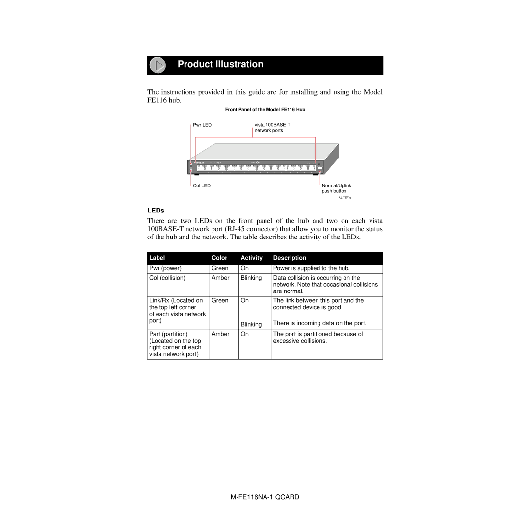
The instructions provided in this guide are for installing and using the Model FE116 hub.
Front Panel of the Model FE116 Hub
Pwr LED | vista |
| network ports |
|
|
|
|
| 100 Mbps | FAST |
|
|
|
|
|
| Link/Rx | Part | ||
Pwr |
|
|
|
|
|
|
|
|
|
|
|
|
|
|
|
|
|
|
|
|
|
|
|
|
|
|
|
|
|
|
|
| Normal/Uplink |
Col |
|
|
|
|
|
|
|
|
|
|
|
|
|
|
|
|
1 | 2 | 3 | 4 | 1 | 2 | 3 | 4 | 9 | 10 | 11 | 12 | 13 | 14 | 15 | 16 |
|
Col LED | Normal/Uplink |
| push button |
| 8493FA |
LEDs
There are two LEDs on the front panel of the hub and two on each vista
Label | Color | Activity | Description |
|
|
|
|
Pwr (power) | Green | On | Power is supplied to the hub. |
|
|
|
|
Col (collision) | Amber | Blinking | Data collision is occurring on the |
|
|
| network. Note that occasional collisions |
|
|
| are normal. |
|
|
|
|
Link/Rx (Located on | Green | On | The link between this port and the |
the top left corner |
|
| connected device is good. |
of each vista network |
|
|
|
port) |
| Blinking | There is incoming data on the port. |
|
| ||
|
|
|
|
Part (partition) | Amber | On | The port is partitioned because of |
(Located on the top |
|
| excessive collisions. |
right corner of each |
|
|
|
vista network port) |
|
|
|
|
|
|
|