Managed Layer 2 Switches GSM7224R and GSM7248R Hardware Installation Guide
GSM7224R Rear Panel
The rear panel has a console port, a redundant power supply connector, and a standard AC power receptacle for the supplied power cord.
|
| Redundant | Power receptacle |
Console | |||
|
| power supply |
|
|
| connector |
|
Figure
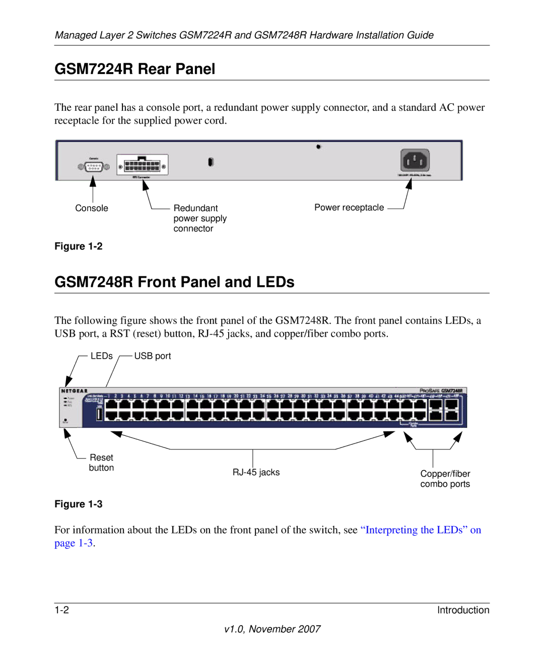
GSM7248R Front Panel and LEDs
The following figure shows the front panel of the GSM7248R. The front panel contains LEDs, a USB port, a RST (reset) button,
LEDs | USB port |
|
|
|
|
Reset |
|
|
|
| |
button |
|
|
|
| |
Copper/fiber | |||||
| |||||
|
|
| combo ports | ||
Figure
For information about the LEDs on the front panel of the switch, see “Interpreting the LEDs” on page
Introduction |