Managed Layer 2 Switches GSM7224R and GSM7248R Hardware Installation Guide
GSM7248R Rear Panel
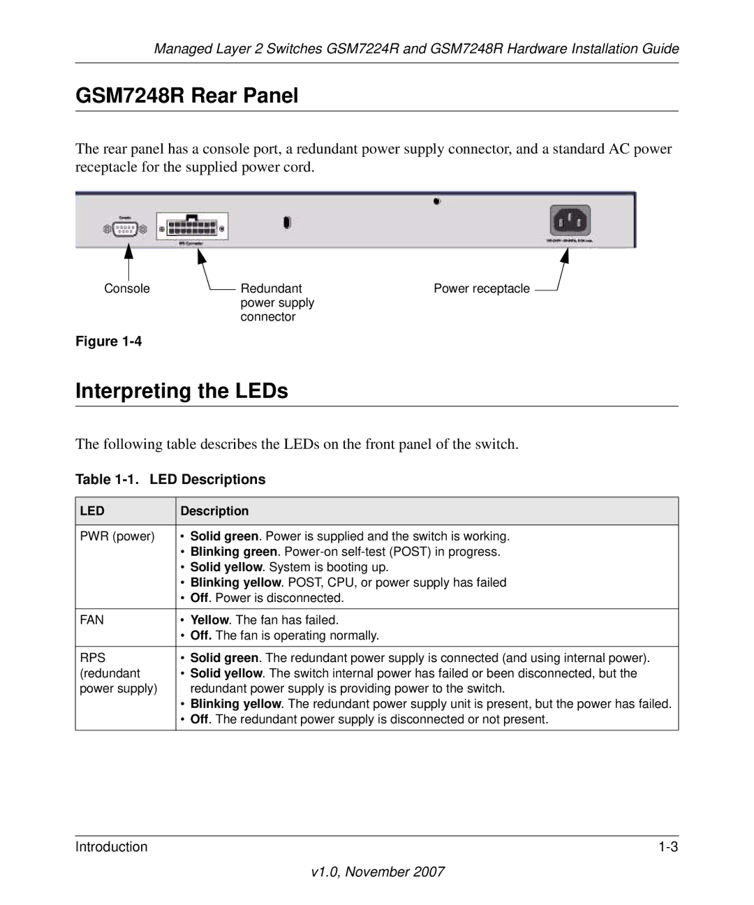
The rear panel has a console port, a redundant power supply connector, and a standard AC power receptacle for the supplied power cord.
Console | Redundant | Power receptacle |
| power supply |
|
| connector |
|
Figure
Interpreting the LEDs
The following table describes the LEDs on the front panel of the switch.
Table 1-1. LED Descriptions
LED | Description |
|
|
PWR (power) | • Solid green. Power is supplied and the switch is working. |
| • Blinking green. |
| • Solid yellow. System is booting up. |
| • Blinking yellow. POST, CPU, or power supply has failed |
| • Off. Power is disconnected. |
FAN | • Yellow. The fan has failed. |
| • Off. The fan is operating normally. |
RPS | • Solid green. The redundant power supply is connected (and using internal power). |
(redundant | • Solid yellow. The switch internal power has failed or been disconnected, but the |
power supply) | redundant power supply is providing power to the switch. |
| • Blinking yellow. The redundant power supply unit is present, but the power has failed. |
| • Off. The redundant power supply is disconnected or not present. |
Introduction |