4 Getting Started User Guide
INTRODUCTION
The Netopia™ Router is designed to be easy to connect, configure, and use. Netopia and your ISP together make it even easier for you to get your router set up and connected to the Internet in a few minutes.
Once you’ve connected your router to your computer and to your telecommunications line and installed a web browser, you’re ready to run the Netopia SmartStart Wizard.
Advanced users can find detailed documentation of advanced configuration options on the Netopia CD in the documentation folio accompanying your Netopia Router.
CONTENTS
This booklet covers the following topics:
■“Making the Physical Connections” on page 4
■“Netopia Router Back Panel Ports” on page 4
■“Connecting to your Network” on page 5
■“Before running SmartStart” on page 5
■“Setting up your Router with the SmartStart Wizard” on page 6
■“Sharing the Connection” on page 10
MAKING THE PHYSICAL CONNECTIONS
Identify the connectors and switches on the back panel and attach the necessar y Netopia Router cables.
1. Connect one of the
(If you are connecting the router to an existing Ethernet hub, use Ethernet port #1 on the router and set the crossover switch to the Uplink position.)
2. Connect one end of one of the
3. Connect the
You should now have: the power adapter plugged in; the Ethernet cable connected between the router and your computer; and the telephone cables connected between the router and the ISDN line jack.
NETOPIA ROUTER BACK PANEL PORTS
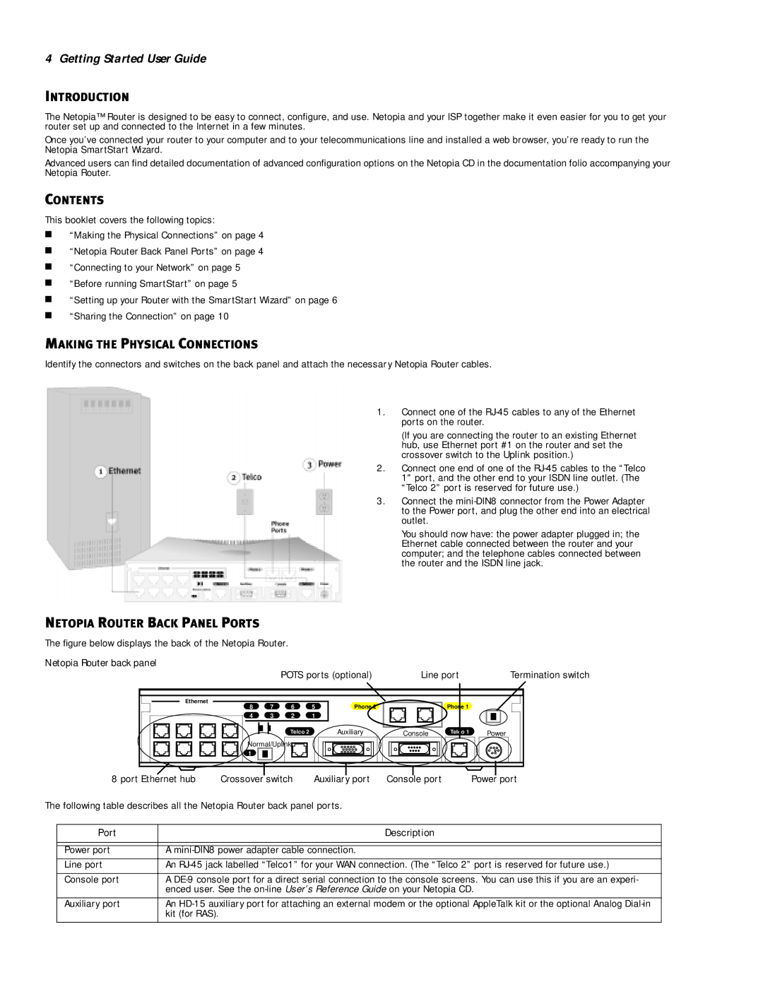
The figure below displays the back of the Netopia Router.
Netopia Router back panel
|
| POTS ports (optional) | Line port | Termination switch | |||
Ethernet | 7 | 6 | 5 |
|
|
|
|
8 | Phone 2 |
| Phone 1 |
| |||
4 | 3 | 2 | 1 |
|
|
|
|
|
| Telco 2 |
| Auxiliary | Console | Telco 1 | Power |
Normal/Uplink |
|
|
|
|
| ||
1 |
|
|
|
|
|
|
|
8 port Ethernet hub | Crossover switch | Auxiliary port | Console port | Power port |
The following table describes all the Netopia Router back panel ports.
Port | Description |
|
|
|
|
Power port | A |
Line port | An |
|
|
Console port | A |
| enced user. See the |
|
|
Auxiliary port | An |
| kit (for RAS). |
|
|