![ZERO CLEARANCE STANDOFF(S) ASSEMBLY](/images/new-backgrounds/52197/5219757x1.webp)
ZERO CLEARANCE STANDOFF(S) ASSEMBLY
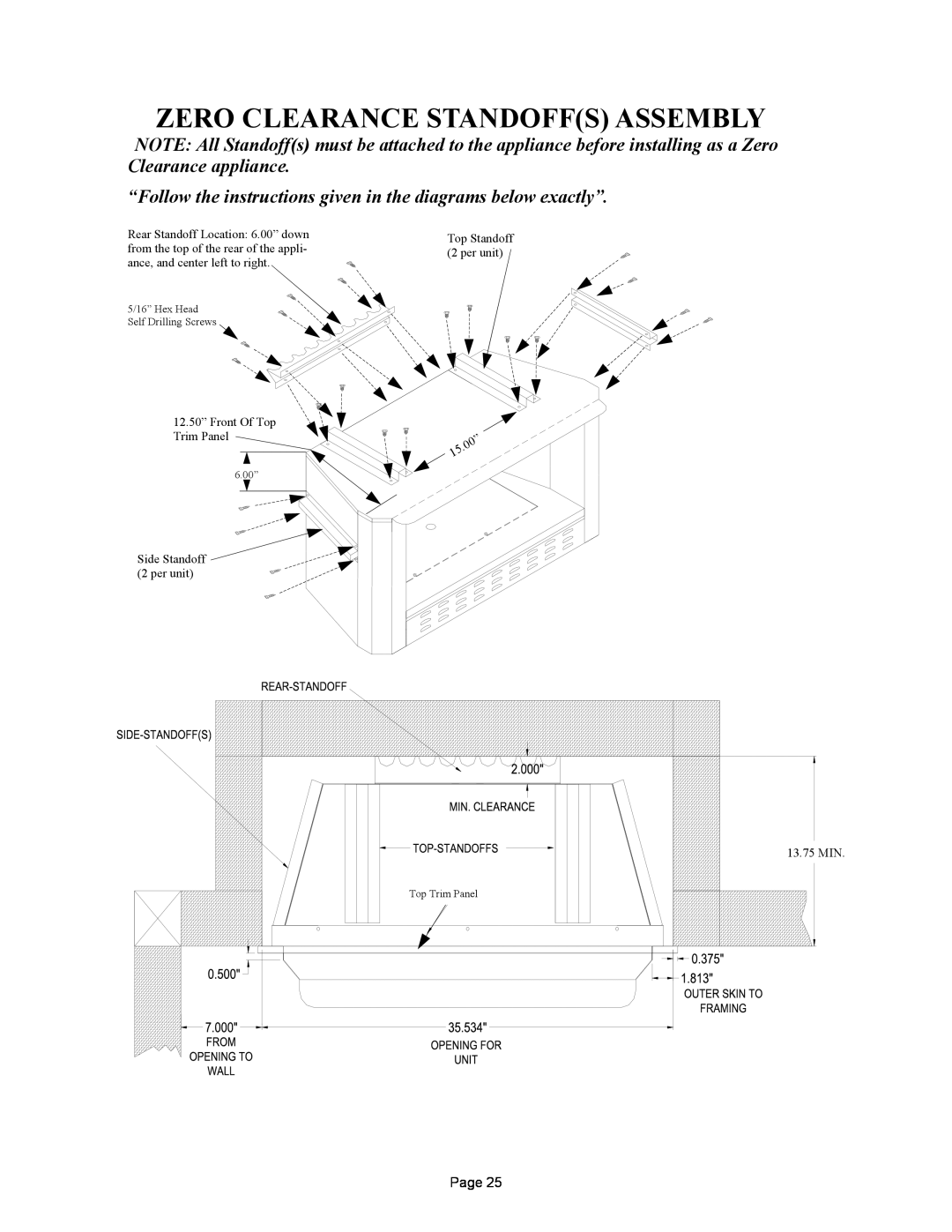
NOTE: All Standoff(s) must be attached to the appliance before installing as a Zero Clearance appliance.
“Follow the instructions given in the diagrams below exactly”.
Rear Standoff Location: 6.00” down from the top of the rear of the appli- ance, and center left to right.
5/16” Hex HeadSelf Drilling Screws
Top Standoff (2 per unit)
12.50” Front Of Top
Trim Panel
6.00”Side Standoff
(2 per unit)![5/16” Hex Head](/images/new-backgrounds/52197/5219757xi3.webp)
![Top Standoff (2 per unit)](/images/new-backgrounds/52197/5219757xi4.webp)
![12.50” Front Of Top](/images/new-backgrounds/52197/5219757xi5.webp)
![6.00”](/images/new-backgrounds/52197/5219757xi6.webp)
![Side Standoff (2 per unit)](/images/new-backgrounds/52197/5219757xi7.webp)
![13.75 MIN.](/images/new-backgrounds/52197/5219757xi8.webp)
![Top Trim Panel](/images/new-backgrounds/52197/5219757xi9.webp)
| ” |
| 0 |
.0 | |
5 |
|
1 |
|
13.75 MIN. |
Top Trim Panel |
Page 25