5.2.6 Mode Selection State
Correct Order of Modes
LRB 7x50 | LRB 7x50 SPD |
Y | MPH |
M | KMH |
+ | + |
|
|
REC1 | Y |
CLR | M |
| SELFTEST3 |
| REC2 |
| CLR |
1)REC1 shows the value of the last measurement, REC 2 the previous measurement and so on.
b. Mode selection state
Pressing MODE button (5) (fig. 1) when the System is in READY mode brings the System to the Mode selecting state. Pressing the Mode button can sequentially scan the Modes. The Mode under selection is being indicated on the Display by flashing of the selectable feature. The "flashing" feature can be selected by pressing the Action button (6).
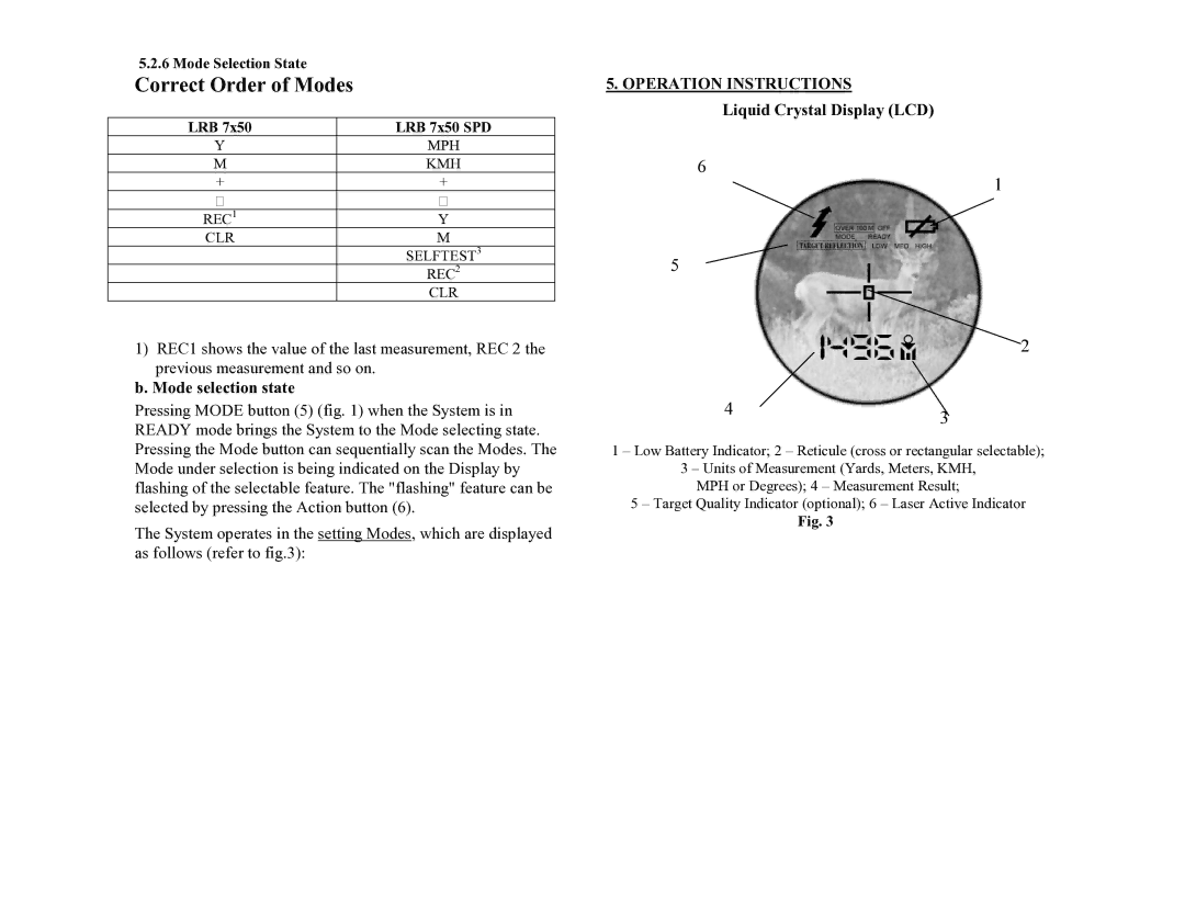
The System operates in the setting Modes, which are displayed as follows (refer to fig.3):
5. OPERATION INSTRUCTIONS
Liquid Crystal Display (LCD)
6
1
5
2
43
1 – Low Battery Indicator; 2 – Reticule (cross or rectangular selectable);
3 – Units of Measurement (Yards, Meters, KMH,
MPH or Degrees); 4 – Measurement Result;
5 – Target Quality Indicator (optional); 6 – Laser Active Indicator
Fig. 3
