INSTALLATION
Before you begin, make sure that all of the cables and wires, as well as the power supply cable will reach the proposed location of the
STEPS:
1) CONNECT POWER TO THE HT-MSU. CHECK LED, DISCONNECT POWER
Plug the supplied 12V DC power supply into an unswitched AC outlet. Plug the connector into the socket marked “Power” on the
wires and cables.
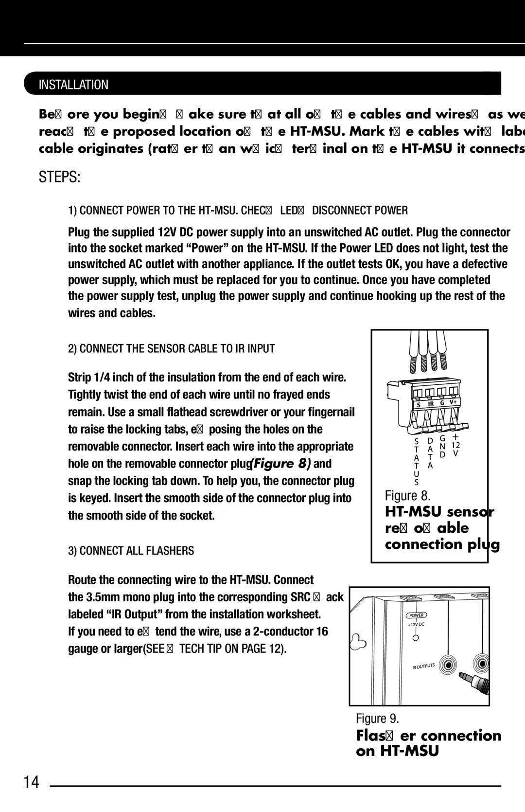
2) CONNECT THE SENSOR CABLE TO IR INPUT
Strip 1/4 inch of the insulation from the end of each wire. Tightly twist the end of each wire until no frayed ends remain. Use a small flathead screwdriver or your fingernail to raise the locking tabs, exposing the holes on the removable connector. Insert each wire into the appropriate hole on the removable connector plug (Figure 8) and snap the locking tab down. To help you, the connector plug is keyed. Insert the smooth side of the connector plug into the smooth side of the socket.
3) CONNECT ALL FLASHERS
Route the connecting wire to the
If you need to extend the wire, use a 2-conductor 16
gauge or larger (SEE “TECH TIP ON PAGE 12).
Figure 8.
Figure 9.
Flasher connection on
14