6.APPENDIX
AltoDrive3.4 Midi standard control
PROGRAM CHANGE
Parameter | Value | Legend |
|
|
|
Preset 01 | 0 | Preset Factory |
|
|
|
Preset 02 to preset 64 | 1, 2, 3,......, 64 | Preset User |
|
|
|
CONTROL CHANGE
Parameter | Controller | Value | setting |
|
| Legend |
|
|
|
|
|
|
|
Bank | 0 | 0, 1, 2 |
|
|
|
|
|
|
|
|
|
|
|
Mode Channel | 22 | 0, 1 | Input Left, Input Right |
|
|
|
Mode Channel | 22 | 2, 3, 4, 5, 6, 7 | Output 1, 2, 3, 4, 5, 6 |
|
|
|
|
|
|
|
|
|
|
Output Volume | 7 | 0,..., 48 | Select Mode Channel |
|
| 12 / 12 dB |
|
| |||||
|
|
|
|
| ||
High Pass Filter | 17 | 0,..., 120 | Mode Channel = 2, 3, 4, 5, 6, 7 Bank=0 | HP Frequency | ||
High Pass Filter | 17 | 0, 1, 2, 3, 4 | Mode Channel = 2, 3, 4, 5, 6, 7 Bank=1 | HP Order | ||
|
|
|
|
| ||
Low Pass Filter | 18 | 0,..., 120 | Mode Channel = 2, 3, 4, 5, 6, 7 Bank=0 | LP Frequency | ||
Low Pass Filter | 18 | 0, 1, 2, 3, 4 | Mode Channel = 2, 3, 4, 5, 6, 7 Bank=1 | LP Order | ||
|
|
|
|
| ||
Delay Line Adj | 19 | 0,..., 127 | Mode Channel = 0, 1, 2, 3, 4, 5 Bank=0 | 508 ms step 4ms | ||
Delay Line Fine | 19 | 0,..., 95 | Mode Channel = 0, 1, 2, 3, 4, 5 Bank=1 | 1995 us step 21us | ||
|
|
|
|
|
|
|
Limiter Threshold | 20 | 0,..., 29 | Mode Channel = 2, 3, 4, 5, 6, 7 Bank=0 |
|
| 29, ..., 0dB |
|
| |||||
Limiter Release | 20 | 0,..., 3 | Mode Channel = 2, 3, 4, 5, 6, 7 Bank=1 | 0.4s, 0.5s, 0.7s, 1.4s | ||
Limiter Attack | 20 | 0,..., 3 | Mode Channel = 2, 3, 4, 5, 6, 7 Bank=2 | 0.05s, 0.1s, 0.2s, 0.3s | ||
|
|
|
|
| ||
Polarity | 21 | 0 | Mode Channel = 2, 3, 4, 5, 6, 7 | Direct | ||
Polarity | 21 | 1 | Mode Channel = 2, 3, 4, 5, 6, 7 | Invers | ||
|
|
|
|
| ||
Filer 01, 02,..., 04 | 12, 13, 14, 15 | 0,..., 120 | Only Mode Channel = 0, 1 (in L, R) | Frequency; Bank=0 | ||
Filer 01, 02,..., 04 | 12, 13, 14, 15 | 0,..., 60 | Only Mode Channel = 0, 1 (in L, R) | Amplitude; Bank=1 | ||
Filer 01, 02,..., 04 | 12, 13, 14, 15 | 0,..., 59 | Only Mode Channel = 0, 1 (in L, R) | Band Width; Bank=2 | ||
|
|
|
|
| ||
Filer 01, 02,..., 05 | 12, 13, 14, 15, 16 | 0,..., 120 | Only Mode Channel = 2, 3, 4, 5, 6, 7 | Frequency; Bank=0 | ||
Filer 01, 02,..., 05 | 12, 13, 14, 15, 16 | 0,..., 60 | Only Mode Channel = 2, 3, 4, 5, 6, 7 | Amplitude; Bank=1 | ||
Filer 01, 02,..., 05 | 12, 13, 14, 15, 16 | 0,..., 59 | Only Mode Channel = 2, 3, 4, 5, 6, 7 | Band Width; Bank=2 | ||
|
|
|
|
| ||
Mute | 23 | 0, 1 | Output 1 Mute OFF, ON | ModeCh=2 | ||
Mute | 23 | 0, 1 | Output 2 Mute OFF, ON | ModeCh=3 | ||
Mute | 23 | 0, 1 | Output 3 Mute OFF, ON | ModeCh=4 | ||
Mute | 23 | 0, 1 | Output 4 Mute OFF, ON | ModeCh=5 | ||
Mute | 23 | 0, 1 | Output 6 Mute OFF, ON | ModeCh=6 | ||
Mute | 23 | 0, 1 | Output 5 Mute OFF, ON | ModeCh=7 | ||
|
|
|
|
| ||
Routing | 24 | 0, 1 | Connect Off/On InputL/R to Output1 | Bank= 0 / Bank=1 | ||
|
|
|
|
| ||
Routing | 25 | 0, 1 | Connect Off/On InputL/R to Output2 | Bank= 0 / Bank=1 | ||
|
|
|
|
| ||
Routing | 26 | 0, 1 | Connect Off/On InputL/R to Output3 | Bank= 0 / Bank=1 | ||
|
|
|
|
| ||
Routing | 27 | 0, 1 | Connect Off/On InputL/R to Output4 | Bank= 0 / Bank=1 | ||
|
|
|
|
| ||
Routing | 28 | 0, 1 | Connect Off/On InputL/R to Output5 | Bank= 0 / Bank=1 | ||
|
|
|
|
| ||
Routing | 29 | 0, 1 | Connect Off/On InputL/R to Output6 | Bank= 0 / Bank=1 | ||
|
|
|
|
|
|
|
Note:
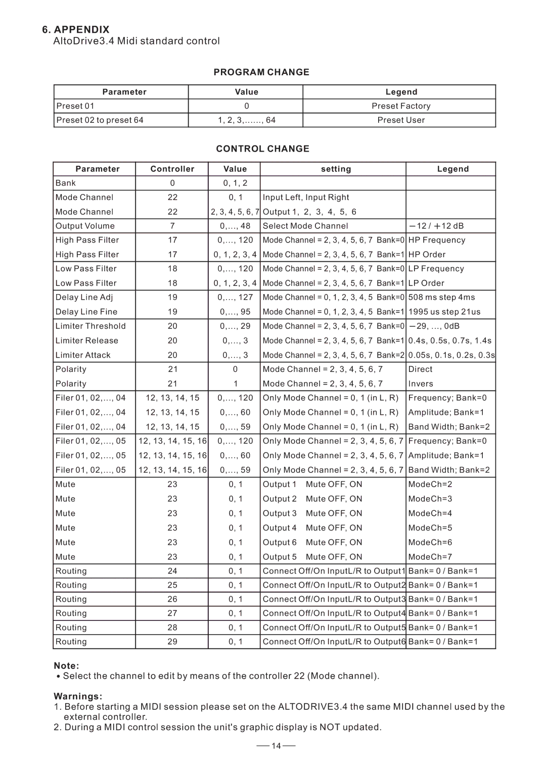
![]() Select the channel to edit by means of the controller 22 (Mode channel).
Select the channel to edit by means of the controller 22 (Mode channel).
Warnings:
1.Before starting a MIDI session please set on the ALTODRIVE3.4 the same MIDI channel used by the external controller.
2.During a MIDI control session the unit's graphic display is NOT updated.
14
