
12 GSM MODULE REMOTE I/O specifications
The Nokia 12 GSM Module Remote I/O stands out as a robust solution for remote monitoring and control in various applications. Designed to seamlessly integrate cellular connectivity with remote input and output functionalities, this module is particularly valuable in industries such as utilities, transportation, and industrial automation.One of the primary features of the Nokia 12 GSM Module is its GSM connectivity, allowing it to operate over existing cellular networks. This connectivity ensures reliable communication across vast distances, making it an ideal choice for remote locations where traditional networking options are impractical. With support for both 2G and 3G networks, the module caters to diverse geographical requirements, providing flexibility depending on regional infrastructure.
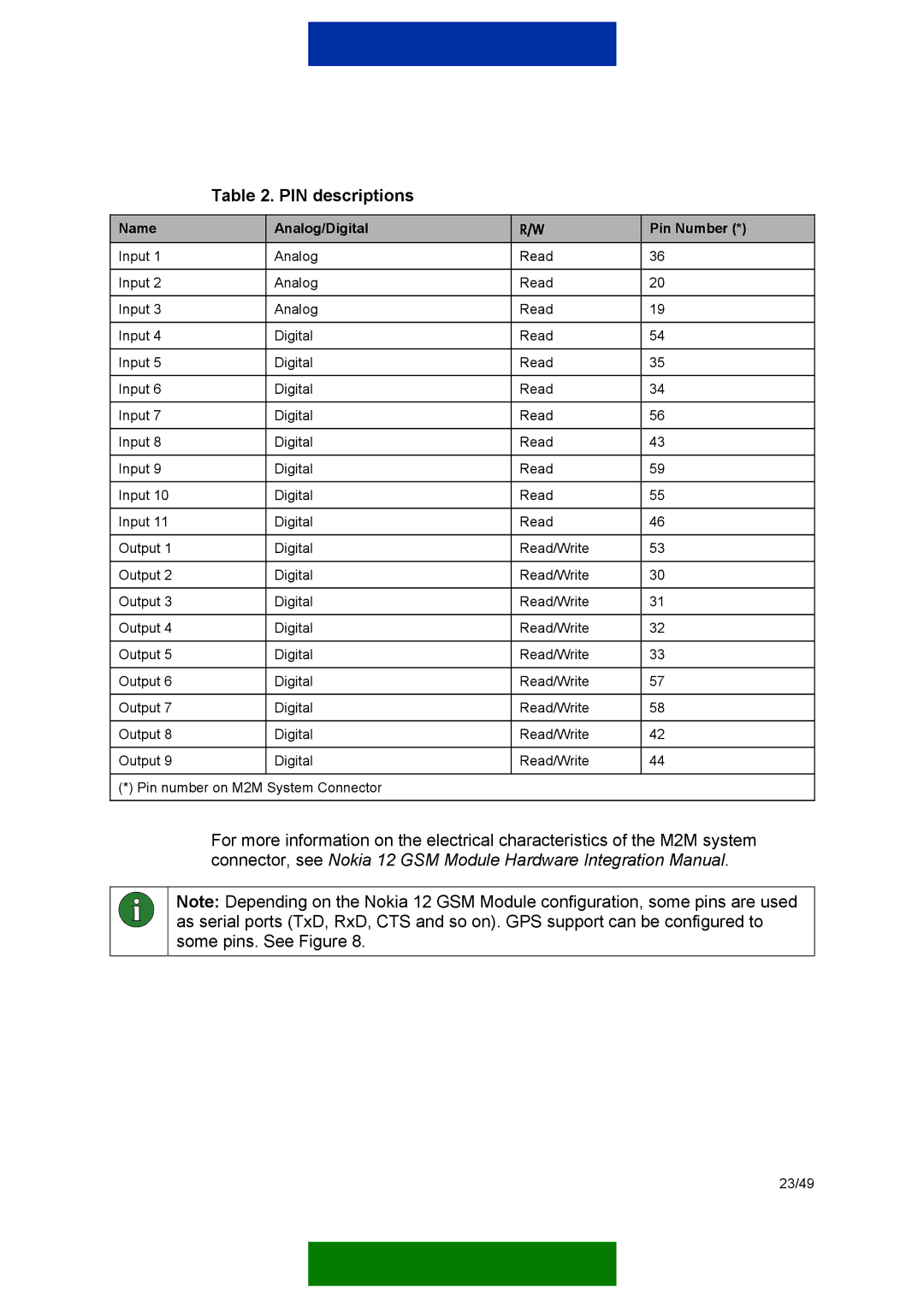
The module supports multiple I/O configurations, including digital and analog inputs and outputs. This versatility enables users to monitor various sensors and control different devices remotely. For instance, it can process data from temperature sensors, pressure gauges, and flow meters while allowing remote control of pumps, valves, and other actuators. This combination of input/output capabilities simplifies the integration into existing systems.
Another notable characteristic of the Nokia 12 GSM Module is its built-in power management features. The module is designed to operate efficiently, utilizing low standby power, which is particularly important for battery-powered applications. This efficiency not only extends the lifespan of power sources but also reduces operational costs, making it a cost-effective solution over time.
Advanced security features are also a hallmark of the Nokia 12 GSM Module. It employs encryption protocols to safeguard data transmissions, protecting sensitive information from unauthorized access. This emphasis on security is essential in industries where data integrity and privacy are paramount.
The module is engineered for rugged environments, boasting a wide temperature operating range and resistance to humidity and dust. Its durable construction ensures that it remains operational in challenging conditions, thereby enhancing its reliability for outdoor or industrial use.
Adding to its capabilities, the Nokia 12 GSM Module can be easily interfaced with various cloud platforms. This compatibility enables real-time data reporting and remote access, empowering users to monitor their systems from anywhere in the world.
In summary, the Nokia 12 GSM Module Remote I/O is a comprehensive solution that provides GSM connectivity, versatile I/O options, energy efficiency, robust security, and durability. These features make it a valuable instrument for enhancing operational efficiency and enabling advanced automation in remote applications.