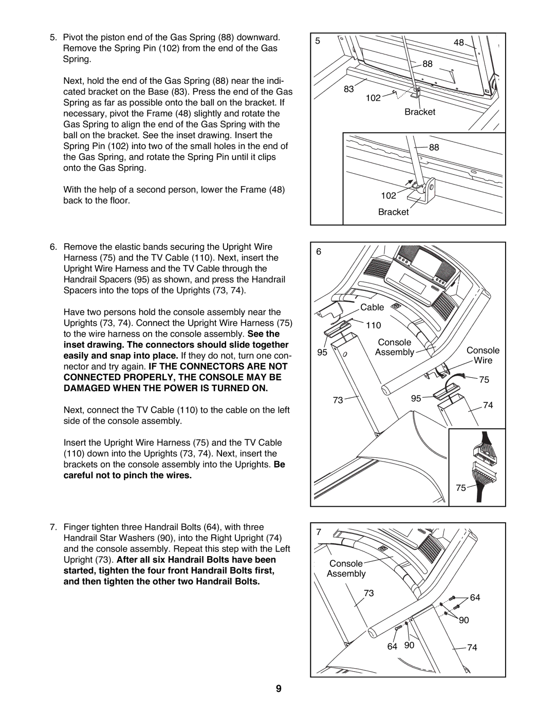
5.Pivot the piston end of the Gas Spring (88) downward. Remove the Spring Pin (102) from the end of the Gas Spring.
Next, hold the end of the Gas Spring (88) near the indi- cated bracket on the Base (83). Press the end of the Gas Spring as far as possible onto the ball on the bracket. If necessary, pivot the Frame (48) slightly and rotate the Gas Spring to align the end of the Gas Spring with the ball on the bracket. See the inset drawing. Insert the Spring Pin (102) into two of the small holes in the end of the Gas Spring, and rotate the Spring Pin until it clips onto the Gas Spring.
With the help of a second person, lower the Frame (48) back to the floor.
6.Remove the elastic bands securing the Upright Wire Harness (75) and the TV Cable (110). Next, insert the Upright Wire Harness and the TV Cable through the Handrail Spacers (95) as shown, and press the Handrail Spacers into the tops of the Uprights (73, 74).
Have two persons hold the console assembly near the Uprights (73, 74). Connect the Upright Wire Harness (75) to the wire harness on the console assembly. See the inset drawing. The connectors should slide together easily and snap into place. If they do not, turn one con- nector and try again. IF THE CONNECTORS ARE NOT
CONNECTED PROPERLY, THE CONSOLE MAY BE DAMAGED WHEN THE POWER IS TURNED ON.
Next, connect the TV Cable (110) to the cable on the left side of the console assembly.
Insert the Upright Wire Harness (75) and the TV Cable (110) down into the Uprights (73, 74). Next, insert the brackets on the console assembly into the Uprights. Be careful not to pinch the wires.
7.Finger tighten three Handrail Bolts (64), with three Handrail Star Washers (90), into the Right Upright (74) and the console assembly. Repeat this step with the Left Upright (73). After all six Handrail Bolts have been started, tighten the four front Handrail Bolts first, and then tighten the other two Handrail Bolts.
9
5 |
| 48 |
| 88 |
|
| 83 |
|
| 102 |
|
| Bracket |
|
| 88 |
|
| 102 |
|
| Bracket |
|
6 |
|
|
| Cable |
|
| 110 |
|
| Console | Console |
95 | Assembly | |
|
| Wire |
|
| 75 |
73 | 95 | 74 |
|
|
|
| 75 |
7 |
|
|
Console |
|
|
Assembly |
|
|
73 |
| 64 |
|
| |
|
| 90 |
64 | 90 | 74 |