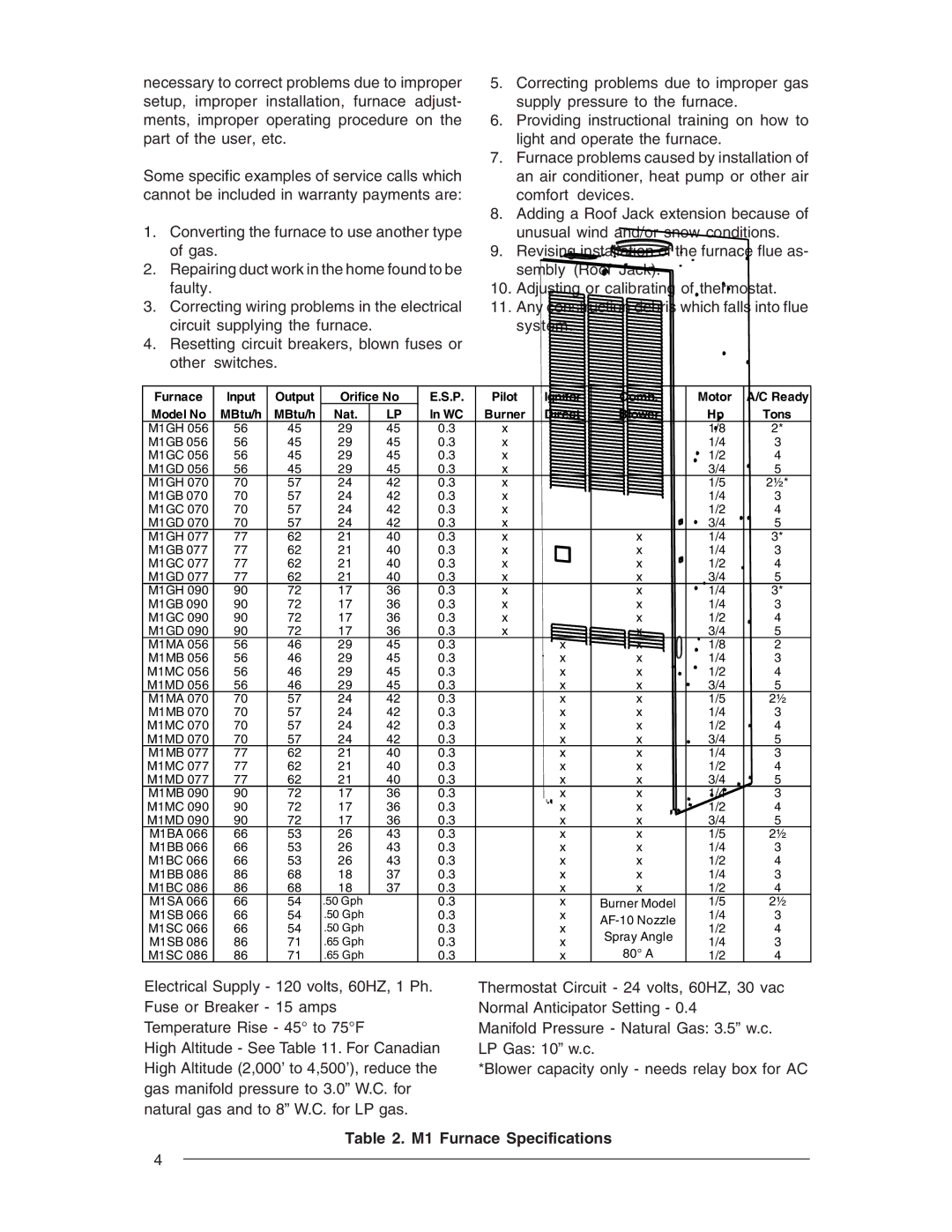
M1M, M1S, M1B, M1G specifications
Nordyne, a renowned player in the HVAC industry, has introduced a range of high-efficiency gas furnaces, including the M1S, M1G, M1B, and M1M models. Each of these furnaces is designed to provide efficient heating solutions tailored to the needs of homeowners.The M1S series is well-known for its reliability and performance. It features a single-stage heating process that delivers consistent warmth to any space. With its multi-speed blower, the M1S ensures quiet and comfortable airflow, adapting seamlessly to varying temperature demands. Its robust construction coupled with an energy-efficient design makes it an ideal choice for those looking for dependable heating without sky-high utility bills.
The M1G model steps it up with a two-stage heating system that offers enhanced comfort and efficiency. By operating at a lower speed during milder conditions, the M1G can effectively reduce energy consumption while still maintaining a cozy environment. It is equipped with a variable-speed blower that not only enhances efficiency but also minimizes noise, making it perfect for residential areas. The M1G is designed with advanced safety features, including an integrated control board that monitors furnace functions to ensure optimal performance.
For those seeking a budget-friendly option without compromising on quality, the M1B model provides a solid performance with its straightforward, reliable single-stage heating. While it may lack some of the advanced features found in higher-end models, the M1B is built for ease of use with straightforward controls and maintenance, making it a great option for families.
The M1M model integrates cutting-edge technology with a focus on maximum efficiency. Featuring a modulating gas valve, this model can adjust its output based on real-time heating requirements. This adaptability ensures that the furnace operates at peak efficiency, significantly lowering energy bills and improving overall comfort. The M1M also boasts advanced diagnostic capabilities that allow for easy troubleshooting, thus reducing maintenance time and costs.
In summary, Nordyne's M1 series furnaces—M1S, M1G, M1B, and M1M—offer a range of options to meet diverse heating needs. With technologies designed for efficiency, reliability, and comfort, Nordyne continues to solidify its reputation as a leader in the HVAC market, providing homeowners with effective heating solutions tailored to their lifestyles and budgets.
