R-410A specifications
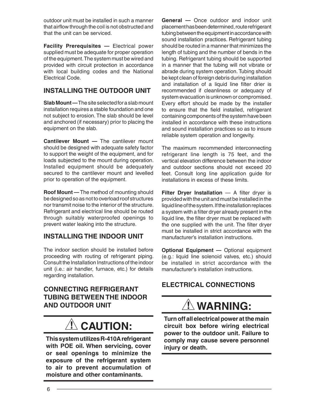
Nordyne R-410A is a widely recognized refrigerant used in modern air conditioning and heat pump systems, known for its efficiency and environmentally friendly attributes. As a hydrofluorocarbon (HFC) refrigerant, R-410A has become the preferred choice for many manufacturers seeking to meet stringent environmental regulations while providing superior cooling performance.One of the main features of R-410A is its higher energy efficiency compared to older refrigerants like R-22. This efficiency is primarily attributed to its higher pressure capabilities, which allow for improved heat transfer and reduced energy consumption in residential and commercial systems. As energy costs continue to rise, the use of R-410A in HVAC systems offers a viable solution for reducing utility bills while maintaining optimal comfort levels.
R-410A is also non-ozone-depleting, which sets it apart from many traditional refrigerants. While older refrigerants have been phased out due to their potential harm to the ozone layer, R-410A presents a sustainable alternative that aligns with environmental goals. It features a zero ozone depletion potential (ODP), making it a responsible choice for installations concerned with ecological impact.
In terms of technology, R-410A works effectively in both air conditioning and heat pump systems, providing reliable cooling in hot conditions and heat in colder months. It is compatible with a variety of system designs and can excel in both residential and commercial applications. Moreover, the thermodynamic properties of R-410A ensure consistent and reliable performance, regardless of the external temperature fluctuations.
Another characteristic of R-410A is its ability to operate at lower temperatures, which enhances its versatility. This capability allows for the design of systems that can function efficiently in a wider range of climate conditions. As a result, HVAC technicians and contractors benefit from its reliability and performance, leading to less frequent maintenance and enhanced customer satisfaction.
Lastly, R-410A systems are equipped with advanced components that improve overall functionality. These systems often include variable-speed compressors, which optimize energy use based on cooling demand, and advanced refrigerant management technologies that ensure safe and efficient operation.
In conclusion, Nordyne R-410A stands out as a superior refrigerant due to its energy efficiency, environmental benefits, and adaptability across a range of HVAC applications. As the industry continues to innovate and shift toward sustainable solutions, R-410A remains at the forefront of refrigerant technology, ensuring homeowners and businesses alike enjoy efficient and eco-friendly cooling options.

