
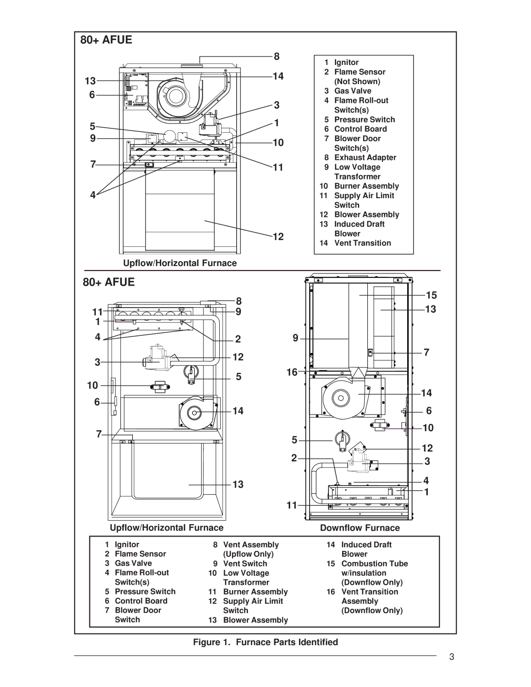
Residential Gas Furnaces specifications
Nordyne Residential Gas Furnaces are a prominent choice for homeowners seeking reliable heating solutions. Renowned for their efficiency and durability, these furnaces are designed to meet the demands of various climates while ensuring optimal home comfort.One of the primary features of Nordyne gas furnaces is their high-efficiency ratings. Many models boast AFUE (Annual Fuel Utilization Efficiency) ratings of 90% or higher, which means they convert a significant percentage of gas into usable heat. This efficiency translates to lower energy bills and a reduced environmental footprint. The advanced heat exchangers used in these furnaces allow for efficient heat transfer and improved performance.
Nordyne also incorporates multi-stage heating technology in their gas furnaces. This feature enables the system to adjust its heating output based on the current demand, promoting energy savings and creating a more consistent indoor temperature. The quiet operation of these units ensures that comfort doesn’t come at the expense of noise, making for a peaceful home environment.
Another standout technology in Nordyne gas furnaces is the use of modulating gas valves. These valves control the amount of gas supplied to the burner, allowing the system to operate at varying speeds. Consequently, this results in more precise temperature control and enhanced energy efficiency, as the furnace can run longer at lower capacities instead of cycling on and off frequently.
Durability is a hallmark of Nordyne products. The furnaces are constructed with high-quality materials that resist wear and tear over time, providing reliability that homeowners can depend on during the cold months. Many models also feature a robust warranty, offering peace of mind regarding long-term performance.
Nordyne's commitment to innovation extends to their intelligent controls and smart technology compatibility. Many models can be integrated with home automation systems, allowing users to monitor and adjust their heating remotely. This connectivity enhances convenience and energy management.
In addition, Nordyne gas furnaces are designed with easy maintenance in mind. Features like accessible filter locations and diagnostic controls simplify routine upkeep, contributing to the longevity of the unit.
In conclusion, Nordyne Residential Gas Furnaces stand out for their energy efficiency, advanced technologies, durability, and user-friendly features. Homeowners can feel confident investing in these heating solutions, knowing they prioritize comfort, performance, and cost-efficiency.