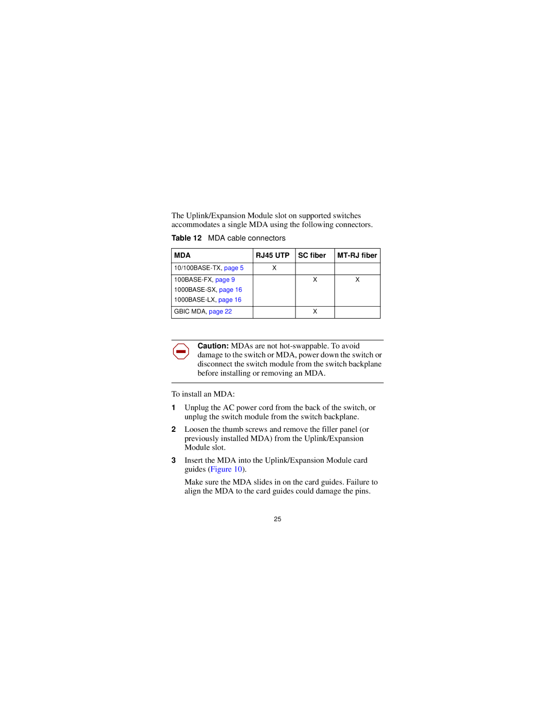
The Uplink/Expansion Module slot on supported switches accommodates a single MDA using the following connectors.
Table 12 MDA cable connectors
MDA | RJ45 UTP | SC fiber | |
|
|
|
|
X |
|
| |
|
|
|
|
| X | X | |
|
|
| |
|
|
| |
|
|
|
|
GBIC MDA, page 22 |
| X |
|
|
|
|
|
Caution: MDAs are not
To install an MDA:
1Unplug the AC power cord from the back of the switch, or unplug the switch module from the switch backplane.
2Loosen the thumb screws and remove the filler panel (or previously installed MDA) from the Uplink/Expansion Module slot.
3Insert the MDA into the Uplink/Expansion Module card guides (Figure 10).
Make sure the MDA slides in on the card guides. Failure to align the MDA to the card guides could damage the pins.
25