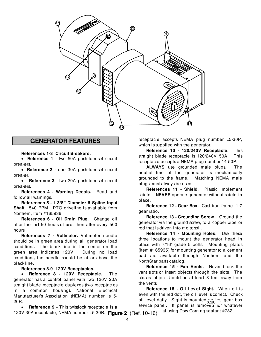
GENERATOR FEATURES
References 1-3 Circuit Breakers.
•Reference 1 - two 50A
•Reference 2 - one 30A
•Reference 3 - two 20A
References 4 - Warning Decals. Read and follow all warnings.
References 5 - 1 3/8” Diameter 6 Spline Input Shaft. 540 RPM. PTO driveline is available from Northern, Item #165936.
References 6 - Oil Drain Plug. Change oil after the first 50 hours of use, then after every 500 hours.
References 7 - Voltmeter. Voltmeter needle should be in green area during all generator load conditions. The black line in the center on the green area indicates 120V. During no load conditions, the needle should be at or above the black line.
References
•Reference 8 - 120V Receptacle. The generator has a control panel with two 120V 20A straight blade receptacle duplexes (two receptacles in a common housing). National Electrical Manufacturer’s Association (NEMA) number is 5- 20R.
•Reference 9 - This twistlock receptacle is a 120V 30A receptacle, NEMA number
receptacle accepts NEMA plug number
Reference 10 - 120/240V Receptacle. This straight blade receptacle is 120/240V 50A. This receptacle accepts a NEMA plug number
ALWAYS use grounded male plugs. The neutral line of the generator is mechanically grounded to the frame. Matching NEMA male plugs must always be used.
References 11 - Shield. Plastic implement shield. NEVER operate generator without shield in place.
Reference 12 - Gear Box. Cast iron frame. 1:7 gear ratio.
Reference 13 - Grounding Screw . Ground the generator via the ground screw, to a copper pipe or rod that is driven into moist soil.
Reference 14 - Mounting Holes. Use these three locations to mount the generator head in place with 7/16” grade 5 bolts. Mounting plates (item #165935) for mounting generator to a cement pad are available through Northern and the NorthStar parts catalog.
Reference 15 - Fan Vents. Never block the vent slots or insert objects through the slots. The closest object should be at least 3 feet away from the vents.
Reference 16 - Oil Level Sight. When oil is even with the red dot, the oil level is correct. Check
oil level daily. Sight is mounted on the gear box 00295
service panel. If panel is removed for whatever
reason, reseal using Dow Corning sealant #732. (Ref.
4
