®
INSTALLATION INSTRUCTIONS
READ & SAVE THESE INSTRUCTIONS!
PLANNING
•Your NuTone Door Chime is designed for
•Handle the door chime carefully, as you would any precision instrument.
WIRING
BE SURE HOUSE POWER IS TURNED OFF WHEN WIRING THE TRANSFORMER. WIRING CONNECTIONS MUST COMPLY WITH LOCAL OR NATIONAL WIRING CODES.
•For chime installation, use NuTone Model 101T Transformer.
NOTE: When fastening chime wiring to wall studs and ceiling joists, care must be taken to avoid possible “shorts” that might be created by allowing staples or clips to cut through the protective wiring insulation.
Refer to Figure 1. Mount the transformer to a convenient junction box
(attic location is not recommended) or circuit breaker box. Connect house
power leads to transformer leads – black to black and white to white.
Refer to Figure 2. Run 2 conductor 18 gauge wire from transformer and the
pushbutton(s) to chime location.
Remove fiberboard shield from front of chime base by gently pulling forward until it disengages from the chime. Bring the wires through the wiring hole in the chime baseplate and fasten the baseplate to the wall through the mounting holes with the screws provided. Connect the transformer and the pushbutton wires to the chime terminal board as shown in Figure 2. Replace fiberboard shield.
SINGLE | 120vAC WIRING | |
FRONT |
| FRONT DOOR |
| DIODE | |
| PUSHBUTTON | |
|
| |
|
| NUTONE 101T |
|
| TRANSFORMER |
TRANS |
| REAR DOOR |
|
| PUSHBUTTON |
REAR | 18 GA. INSULATED |
|
| ||
TERMINAL |
| |
| FIGURE 2 | |
BOARD |
| |
Front pushbutton must have diode (supplied) assembled across the screw terminals as shown in Figure 3.
NOTE: Upon completion of installation, if the chime does not operate properly, check the pushbutton(s) for poor contact or loose connections. Be certain wires are not touching the tone bars.
Lighted Door Chimes
LA-156PR, LA-163, LA-164 or LA-165 Series
INSTALLING THE PUSHBUTTONS
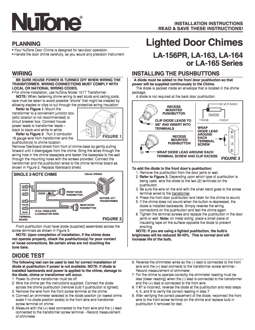
A diode must be added to the front door pushbutton so that power will be supplied continuously to the Chime.
The diode is packed inside an envelope that is located in the chime package.
A diode is not required at the back door pushbutton.
RECESS |
| SILVER BAND |
|
| |
MOUNTED |
|
|
PUSHBUTTON | DIODE |
|
|
| |
CLIP DIODE LEADS TO | TRANS | FRONT |
3/8" AND INSERT INTO | WRAP |
|
TERMINALS |
| |
| DIODE LEAD |
|
RECESS | AROUND |
|
EACH |
| |
MOUNTED |
| |
TERMINAL |
| |
PUSHBUTTON |
| |
SCREW |
| |
|
| |
WRAP DIODE LEAD AROUND EACH |
| |
TERMINAL SCREW AND CLIP EXCESS | FIGURE 3 | |
To add the diode to the front door's pushbutton:
1.Remove the pushbutton from the door jamb or wall.
2.Refer to Figure 3. Depending upon which type of pushbutton is being used, wire the diode to the two (2) terminals on the pushbutton.
3.Be sure the wire on the end with the silver band goes to the screw terminal wired to the transformer.
4.Press the front door pushbutton and listen for the chime to sound.
5.If the chime does not sound when the button is depressed, the diode is installed backwards. Simply reverse the wiring connections on the pushbutton and test the chime again.
6.Tighten the terminal screws and replace the pushbutton in the door
jamb or wall. Note: on metal siding, place a small piece of insulating tape on the surface opposite the diode to prevent shorting.
NOTE: If you are using a lighted pushbutton, the bulb's brightness will be reduced
DIODE TEST
The following test can be used to test for correct installation of diode at pushbutton if power is not available. NOTE: If diode is installed backwards and power is applied to the chime, damage to the diode, chime or transformer will occur.
1.Power to chime transformer must be off.
2.Wire the chime per the instructions supplied. Connect the diode across the chime pushbutton (remove bulb if pushbutton is lighted).
3.Remove the wire from the front screw terminal at the chime.
4.Connect an ohmmeter selected to the diode position (or lowest ohms scale if no diode position exists) to the front wire and transfomer screw terminal on chime.
5.Measure with the (+) lead connected to the front wire and the
6.Reverse the ohmmeter wires so the
7.For the chime to operate correctly the ohmmeter reading must be less (lower reading) when the
8.If #7 is incorrect, reverse the diode at the pushbutton and redo steps 4, 5, and 6 to verify the correct reading in step 7.
9.After verifying the correct placement of the diode, reconnect the front wire to the front screw terminal on the chime and replace bulb in pushbutton if removed for test.