
QTXN110HFLT specifications
The NuTone QTXN110HFLT is a sophisticated and highly efficient bathroom ventilation fan, tailored to meet the demands of modern homes while ensuring comfort and air quality. This model, part of NuTone's innovative line, stands out with its robust features and advanced technologies, making it an ideal choice for homeowners aiming to enhance their bathroom environment.One of the main highlights of the QTXN110HFLT is its powerful ventilation capability. With a fan rating of 110 CFM, it is designed to quickly and effectively expel moisture and odors, preventing the buildup of mold and mildew in humid spaces. This promotes a healthier environment, especially in bathrooms where humidity levels can fluctuate dramatically.
The Quieter technology is another significant feature of this model. Operating at just 0.7 sones, the QTXN110HFLT ensures whisper-quiet performance without sacrificing efficiency. This makes it perfect for use in bathrooms where a serene atmosphere is desired. The combination of high performance and quiet operation sets this fan apart from many competitors in the market.
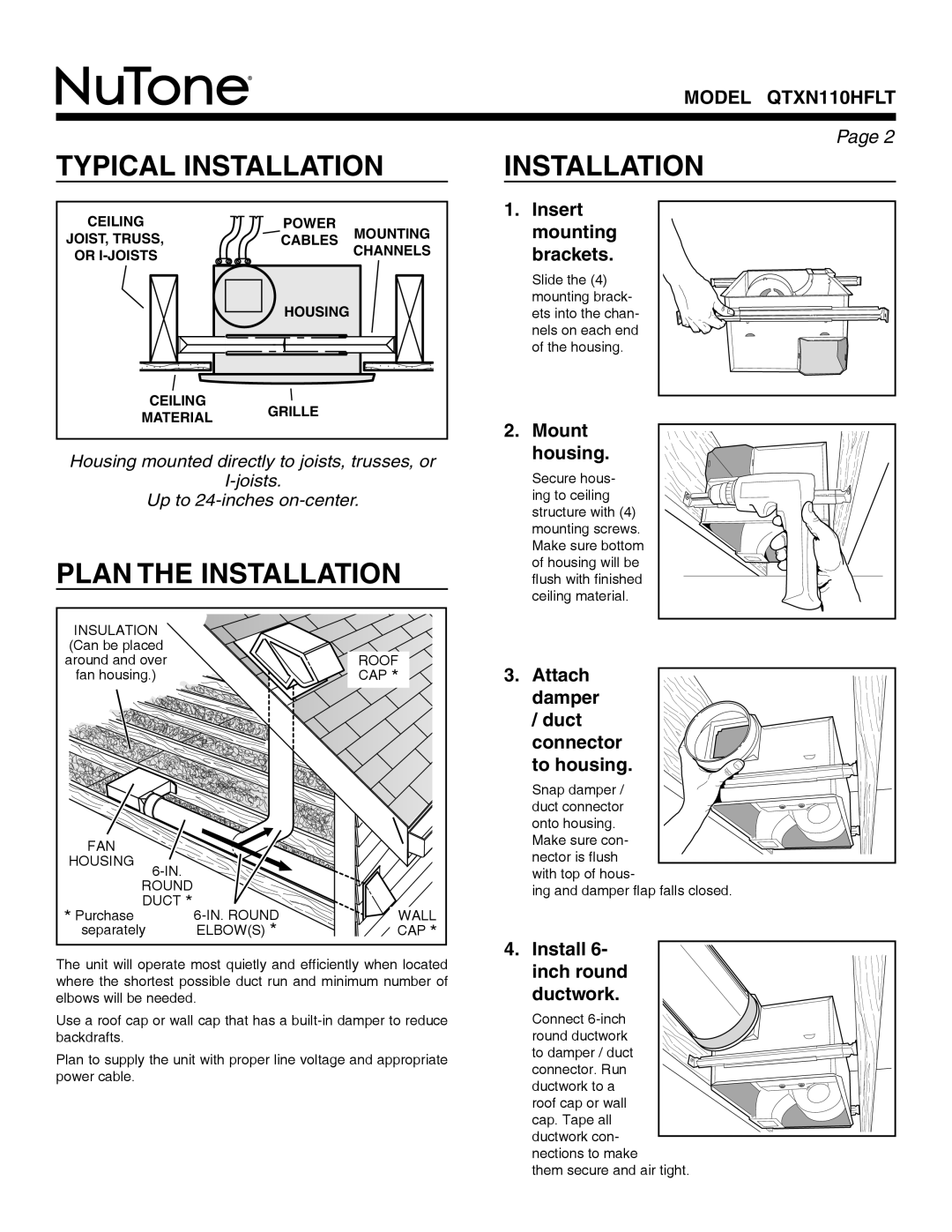
In terms of installation, the NuTone QTXN110HFLT is designed for easy and flexible mounting. It can be installed in either new construction or as a retrofit into existing spaces. The fan comes ready to facilitate the installation process, equipped with a sturdy housing that fits standard duct sizes. Additionally, users will appreciate the included duct adapter, which simplifies connectivity to the ductwork.
Energy efficiency is another critical attribute of the QTXN110HFLT. It features an Energy Star certification, meaning it consumes less power than non-certified models while still delivering outstanding performance. This not only reduces energy costs but also aligns with eco-conscious living standards.
The design of the fan is equally appealing, offering sleek aesthetics that can seamlessly blend in with a variety of bathroom decors. The low-profile grille is unobtrusive yet elegant, enhancing the overall look of the space.
Additionally, the QTXN110HFLT is equipped with the Flexi-Hinge feature. This innovative aspect allows the fan to adjust the angle of the vent, ensuring optimal airflow control and maximum ventilation performance.
Overall, the NuTone QTXN110HFLT is a leading choice for those seeking an effective, quiet, and energy-efficient bathroom ventilation solution, combining practical features with modern technology to improve indoor air quality and comfort.