4 ELECTRICAL INSTALLATION…
Remote Set Point ![]() % ^ &
% ^ &
Process Variable ![]() @ £ $
@ £ $
Sleeved ![]()
Link + –
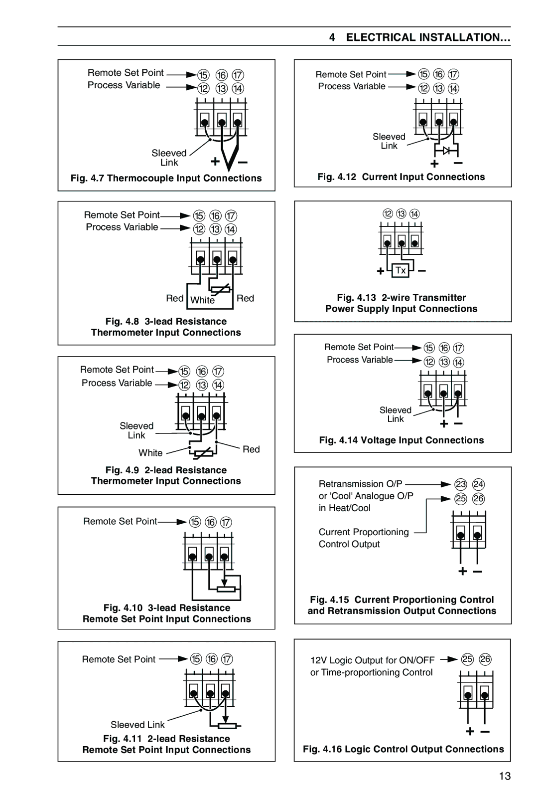
Fig. 4.7 Thermocouple Input Connections
Remote Set Point![]() % ^ &
% ^ &
Process Variable ![]() @ £ $
@ £ $
Red White | Red |
Fig. 4.8 3-lead Resistance
Thermometer Input Connections
Remote Set Point | % ^ & |
Process Variable | @ £ $ |
Sleeved |
|
Link |
|
White | Red |
| |
Fig. 4.9 | |
Thermometer Input Connections | |
Remote Set Point | % ^ & |
Fig. 4.10 | |
Remote Set Point Input Connections | |
Remote Set Point | % ^ & |
Sleeved Link |
|
Fig. 4.11 | |
Remote Set Point Input Connections | |
Remote Set Point ![]() % ^ &
% ^ &
Process Variable ![]() @ £ $
@ £ $
Sleeved
Link
+ | – |
Fig. 4.12 Current Input Connections
@ £ $
+  Tx
Tx  –
–
Fig. 4.13 2-wire Transmitter
Power Supply Input Connections
Remote Set Point![]() % ^ &
% ^ &
Process Variable ![]() @ £ $
@ £ $
|
|
|
|
|
|
|
|
|
|
|
|
|
|
|
|
|
|
|
|
|
|
|
|
|
|
|
|
|
|
|
|
|
|
|
|
|
|
|
|
|
|
|
|
|
|
|
|
|
|
|
|
|
|
|
|
|
|
|
|
|
|
|
|
|
|
|
|
|
|
Sleeved |
|
|
|
|
|
|
|
|
|
|
|
| |
|
|
|
|
|
|
|
|
|
|
|
| ||
Link | + |
| – | ||||||||||
|
|
| |||||||||||
Fig. 4.14 Voltage Input Connections
Retransmission O/P ![]() 23 24
23 24
or 'Cool' Analogue O/P ![]() 25 26 in Heat/Cool
25 26 in Heat/Cool
Current Proportioning
Control Output
+ –
Fig. 4.15 Current Proportioning Control and Retransmission Output Connections
12V Logic Output for ON/OFF | 25 | 26 |
or |
|
|
| + | – |
Fig. 4.16 Logic Control Output Connections | ||
|
| 13 |
