…4 ELECTRICAL INSTALLATION
4.7Output Connections
Make connections as shown in Figs 4.15 and
4.16.
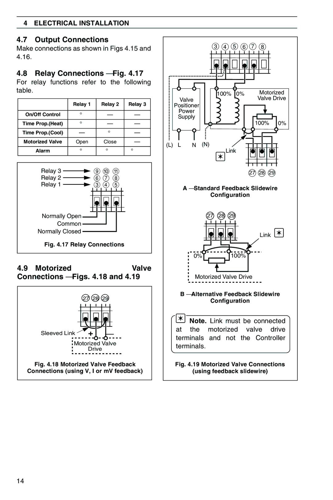
4.8Relay Connections – Fig. 4.17
For relay functions refer to the following table.
| Relay 1 | Relay 2 | Relay 3 |
|
|
|
|
On/Off Control | ✓ | — | — |
|
|
|
|
Time Prop.(Heat) | ✓ | — | — |
|
|
|
|
Time Prop.(Cool) | — | ✓ | — |
|
|
|
|
Motorized Valve | Open | Close | — |
|
|
|
|
Alarm | ✓ | ✓ | ✓ |
|
|
|
|
Relay 3 ![]() 9 0 !
9 0 !
Relay 2 ![]() 6 7 8
6 7 8
Relay 1 ![]() 3 4 5
3 4 5
Normally Open
Common
Normally Closed
Fig. 4.17 Relay Connections
4.9 Motorized |
|
| Valve |
Connections – Figs. 4.18 and 4.19 | |||
| 27 | 28 | 29 |
Sleeved Link | + | – | |
Motorized Valve | |||
| Drive |
| |
Fig. 4.18 Motorized Valve Feedback
Connections (using V, I or mV feedback)
|
|
| 3 4 5 6 7 8 |
|
| |||
|
|
|
| 100% 0% | Motorized | |||
| Valve |
|
|
| Valve Drive | |||
| Positioner |
|
|
|
|
|
| |
| Power |
|
|
|
|
|
| |
| Supply |
|
| 100% | 0% | |||
|
|
|
|
| ||||
(L) | L | N | (N) |
| Link |
|
|
|
|
|
|
|
|
|
|
| |
|
|
|
|
| 27 | 28 | 29 |
|
|
| A – Standard Feedback Slidewire |
| |||||
|
|
| Configuration |
|
|
| ||
|
|
| 27 | 28 | 29 |
|
|
|
|
|
|
|
|
| Link |
| |
|
| 0% |
| 100% |
|
|
| |
|
| Motorized Valve Drive |
|
|
| |||
| B – Alternative Feedback Slidewire | |||||||
|
|
| Configuration |
|
|
| ||
|
| Note. Link must be connected | ||||||
| at the motorized valve drive | |||||||
| terminals and not the Controller | |||||||
| terminals. |
|
|
|
|
| ||
| Fig. 4.19 Motorized Valve Connections | |||||||
|
| (using feedback slidewire) |
|
| ||||
14