OUTPUT WIRING
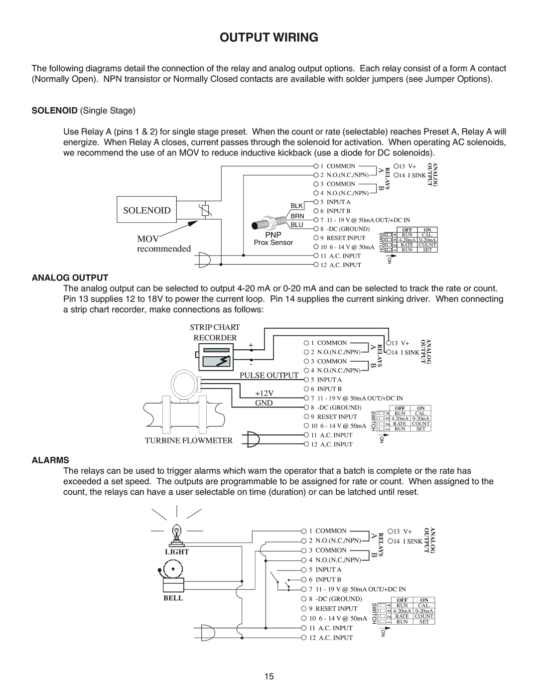
The following diagrams detail the connection of the relay and analog output options. Each relay consist of a form A contact (Normally Open). NPN transistor or Normally Closed contacts are available with solder jumpers (see Jumper Options).
SOLENOID (Single Stage)
Use Relay A (pins 1 & 2) for single stage preset. When the count or rate (selectable) reaches Preset A, Relay A will energize. When Relay A closes, current passes through the solenoid for activation. When operating AC solenoids, we recommend the use of an MOV to reduce inductive kickback (use a diode for DC solenoids).
SOLENOID
MOV recommended
BLK
BRN
BLU
PNP
Prox Sensor
1 | COMMON |
|
| RELAYS AB |
| 13 V+ |
| ANALOG OUTPUT | ||
|
|
|
|
|
|
|
| |||
2 | N.O.(N.C./NPN) |
|
|
|
|
| 14 I SINK |
| ||
|
|
|
|
|
| |||||
3 | COMMON |
|
|
|
|
|
|
|
|
|
4 | N.O.(N.C./NPN) |
|
|
|
|
|
|
|
| |
|
|
|
|
|
|
|
| |||
5 | INPUT A |
|
|
|
|
|
|
| ||
6 | INPUT B |
|
|
|
|
|
|
| ||
7 | 11 - 19 V @ 50mA OUT/+DC IN |
|
| |||||||
8 |
|
|
|
|
|
| ||||
|
|
|
| OFF | ON | |||||
10 6 - 14 V @ 50mA | SWITCH |
|
| 213 4 | RUN | SET | ||||
9 | RESET INPUT |
|
|
|
| RUN | CAL. | |||
|
|
|
| |||||||
|
|
|
|
|
|
|
| RATE | COUNT | |
11 A.C. INPUT |
|
|
|
|
|
|
| |||
|
|
|
|
|
|
| ||||
|
| ON |
|
|
|
| ||||
12 A.C. INPUT |
|
|
|
|
|
| ||||
|
|
|
|
|
|
| ||||
ANALOG OUTPUT
The analog output can be selected to output
STRIP CHART
RECORDER |
+ |
- |
PULSE OUTPUT
+12V GND
TURBINE FLOWMETER
1 | COMMON |
|
| RELAYS AB |
| 13 V+ |
| ANALOG OUTPUT | ||
|
|
|
|
|
|
|
| |||
2 | N.O.(N.C./NPN) |
|
|
|
|
| 14 I SINK |
| ||
|
|
|
|
|
| |||||
3 | COMMON |
|
|
|
|
|
|
|
|
|
|
|
|
|
|
|
|
|
| ||
4 | N.O.(N.C./NPN) |
|
|
|
|
|
|
|
| |
|
|
|
|
|
|
|
| |||
5 | INPUT A |
|
|
|
|
|
|
| ||
6 | INPUT B |
|
|
|
|
|
|
| ||
7 | 11 - 19 V @ 50mA OUT/+DC IN |
|
| |||||||
8 |
|
|
|
|
|
| ||||
|
|
|
| OFF | ON | |||||
10 6 - 14 V @ 50mA | SWITCH |
|
| 213 4 | RUN | SET | ||||
9 | RESET INPUT |
|
|
|
| RUN | CAL. | |||
|
|
|
| |||||||
|
|
|
|
|
|
|
| RATE | COUNT | |
11 A.C. INPUT |
|
|
|
|
|
|
| |||
|
|
|
|
|
|
| ||||
|
| ON |
|
|
|
| ||||
12 A.C. INPUT |
|
|
|
|
|
| ||||
|
|
|
|
|
|
| ||||
ALARMS
The relays can be used to trigger alarms which warn the operator that a batch is complete or the rate has exceeded a set speed. The outputs are programmable to be assigned for rate or count. When assigned to the count, the relays can have a user selectable on time (duration) or can be latched until reset.
LIGHT
BELL
1 | COMMON |
|
| RELAYS AB |
| 13 V+ |
| ANALOG OUTPUT | ||||
|
|
|
|
|
|
|
|
|
| |||
2 | N.O.(N.C./NPN) |
|
|
|
|
|
| 14 I SINK |
|
| ||
|
|
|
|
|
|
|
| |||||
3 | COMMON |
|
|
|
|
|
|
|
|
|
|
|
|
|
|
|
|
|
|
|
|
|
| ||
4 | N.O.(N.C./NPN) |
|
|
|
|
|
|
|
|
|
| |
|
|
|
|
|
|
|
|
|
| |||
5 | INPUT A |
|
|
|
|
|
|
|
|
| ||
6 | INPUT B |
|
|
|
|
|
|
|
|
| ||
7 | 11 - 19 V @ 50mA OUT/+DC IN |
|
|
| ||||||||
8 |
|
|
|
|
|
|
|
| ||||
|
|
|
|
| OFF | ON | ||||||
10 6 - 14 V @ 50mA | SWITCH |
|
|
| 213 4 | RUN | SET |
| ||||
9 | RESET INPUT |
|
|
|
|
| RUN | CAL. |
| |||
|
|
|
|
|
| |||||||
|
|
|
|
|
|
|
|
| RATE | COUNT |
| |
11 A.C. INPUT |
|
|
|
|
|
|
|
|
| |||
|
|
|
|
|
|
|
|
| ||||
|
| ON |
|
|
|
|
| |||||
12 A.C. INPUT |
|
|
|
|
|
|
| |||||
|
|
|
|
|
|
|
|
| ||||
15
