8.5.- EXCITATION VOLTAGE FOR SENSORS
The unit supplies the Excitation Voltage for sensors, through control lines connector.
If the current required for the sensors installed is more than 100 mA then do not use this terminal. Install other external power supply. See paragraph 5 for technical specifications
9.- POWER-UP AND OPERATION
9.1.- REAL TIME CLOCK
At
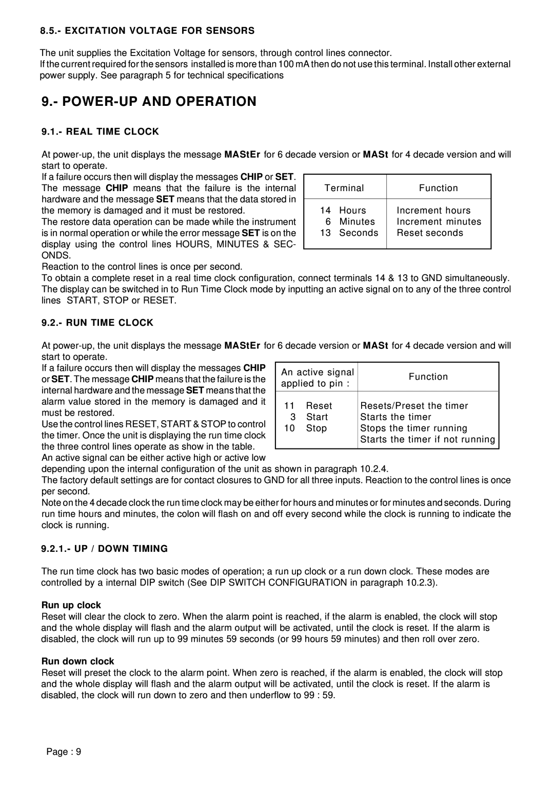
If a failure occurs then will display the messages CHIP or SET. The message CHIP means that the failure is the internal hardware and the message SET means that the data stored in the memory is damaged and it must be restored.
The restore data operation can be made while the instrument is in normal operation or while the error message SET is on the display using the control lines HOURS, MINUTES & SEC-
Terminal | Function | |
|
|
|
14 | Hours | Increment hours |
6 | Minutes | Increment minutes |
13 | Seconds | Reset seconds |
|
|
|
ONDS.
Reaction to the control lines is once per second.
To obtain a complete reset in a real time clock configuration, connect terminals 14 & 13 to GND simultaneously. The display can be switched in to Run Time Clock mode by inputting an active signal on to any of the three control lines START, STOP or RESET.
9.2.- RUN TIME CLOCK
At
If a failure occurs then will display the messages CHIP | An active signal | Function | ||
or SET. The message CHIP means that the failure is the | ||||
applied to pin : | ||||
internal hardware and the message SET means that the |
| |||
|
|
| ||
|
|
| ||
alarm value stored in the memory is damaged and it | 11 | Reset | Resets/Preset the timer | |
must be restored. | ||||
3 | Start | Starts the timer | ||
Use the control lines RESET, START & STOP to control | ||||
10 | Stop | Stops the timer running | ||
the timer. Once the unit is displaying the run time clock | ||||
|
| Starts the timer if not running | ||
the three control lines operate as show in the table. |
|
| ||
|
|
| ||
An active signal can be either active high or active low
depending upon the internal configuration of the unit as shown in paragraph 10.2.4.
The factory default settings are for contact closures to GND for all three inputs. Reaction to the control lines is once per second.
Note on the 4 decade clock the run time clock may be either for hours and minutes or for minutes and seconds. During run time hours and minutes, the colon will flash on and off every second while the clock is running to indicate the clock is running.
9.2.1.- UP / DOWN TIMING
The run time clock has two basic modes of operation; a run up clock or a run down clock. These modes are controlled by a internal DIP switch (See DIP SWITCH CONFIGURATION in paragraph 10.2.3).
Run up clock
Reset will clear the clock to zero. When the alarm point is reached, if the alarm is enabled, the clock will stop and the whole display will flash and the alarm output will be activated, until the clock is reset. If the alarm is disabled, the clock will run up to 99 minutes 59 seconds (or 99 hours 59 minutes) and then roll over zero.
Run down clock
Reset will preset the clock to the alarm point. When zero is reached, if the alarm is enabled, the clock will stop and the whole display will flash and the alarm output will be activated, until the clock is reset. If the alarm is disabled, the clock will run down to zero and then underflow to 99 : 59.
Page : 9
