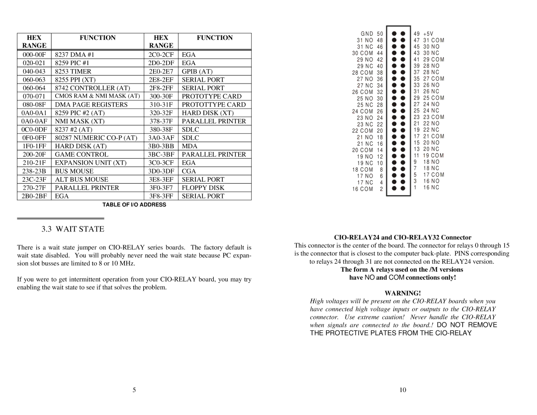
CIO-RELAY24, CIO-RELAY08, CIO-RELAY16, CIO-RELAY32 specifications
Omega Speaker Systems has established itself as a leader in providing innovative solutions for audio control and distribution, particularly with its range of relay modules designed for professional audio environments. Among the standout products in their lineup are the CIO-RELAY16, CIO-RELAY08, CIO-RELAY24, and CIO-RELAY32. Each of these relay modules is engineered to offer unparalleled flexibility, reliability, and ease of integration.The CIO-RELAY16 features 16 channels of relay control, allowing for the management of multiple audio zones or devices simultaneously. This module supports a variety of control protocols, enabling seamless integration into existing systems. With robust circuitry and protective measures, it ensures reliable operation even in demanding environments.
In contrast, the CIO-RELAY08 focuses on more compact needs, delivering 8 relay channels for smaller setups. This module is particularly well-suited for installations where space is at a premium but still provides essential control functions. The simplicity of this model makes it an excellent choice for user-friendly applications, allowing operators to manage audio routing without complexity.
The CIO-RELAY24 extends the capabilities of its predecessors by offering 24 relay channels, making it ideal for expansive audio setups requiring extensive control. Its advanced features include remote activation and monitoring capabilities, making it a suitable choice for large venues or multi-room installations. The CIO-RELAY24 exhibits excellent compatibility with various audio equipment, ensuring that users can create versatile and customized audio environments.
Meanwhile, the CIO-RELAY32 takes versatility to the next level, providing 32 relay channels for the most demanding applications. This module is specifically designed for large-scale installations where maximum control is essential. It incorporates state-of-the-art technologies like smart routing and energy efficiency features, which are critical for modern audio applications that are both high-performance and environmentally conscious.
All models in the CIO-RELAY series share common characteristics such as durable construction, intuitive installation processes, and the ability to work with a multitude of control systems. The devices are equipped with LED status indicators for real-time feedback, ensuring that users can monitor system performance with ease. The modules are designed to be user-friendly, minimizing the learning curve associated with complex audio control systems.
In conclusion, the CIO-RELAY series by Omega Speaker Systems presents a powerful array of relay modules designed to meet diverse audio control needs. With their distinct features, these products cater to both small and large installations, ensuring that users can achieve optimal audio management in any environment.

