HIGH AND LOW PEAKS
A useful feature provided by the DPS3301 system is its ability to track high and low temperature peaks. This function is useful if a process must be left unattended for a long period of time, and it is necessary to find temperature extremes during the unattended period.
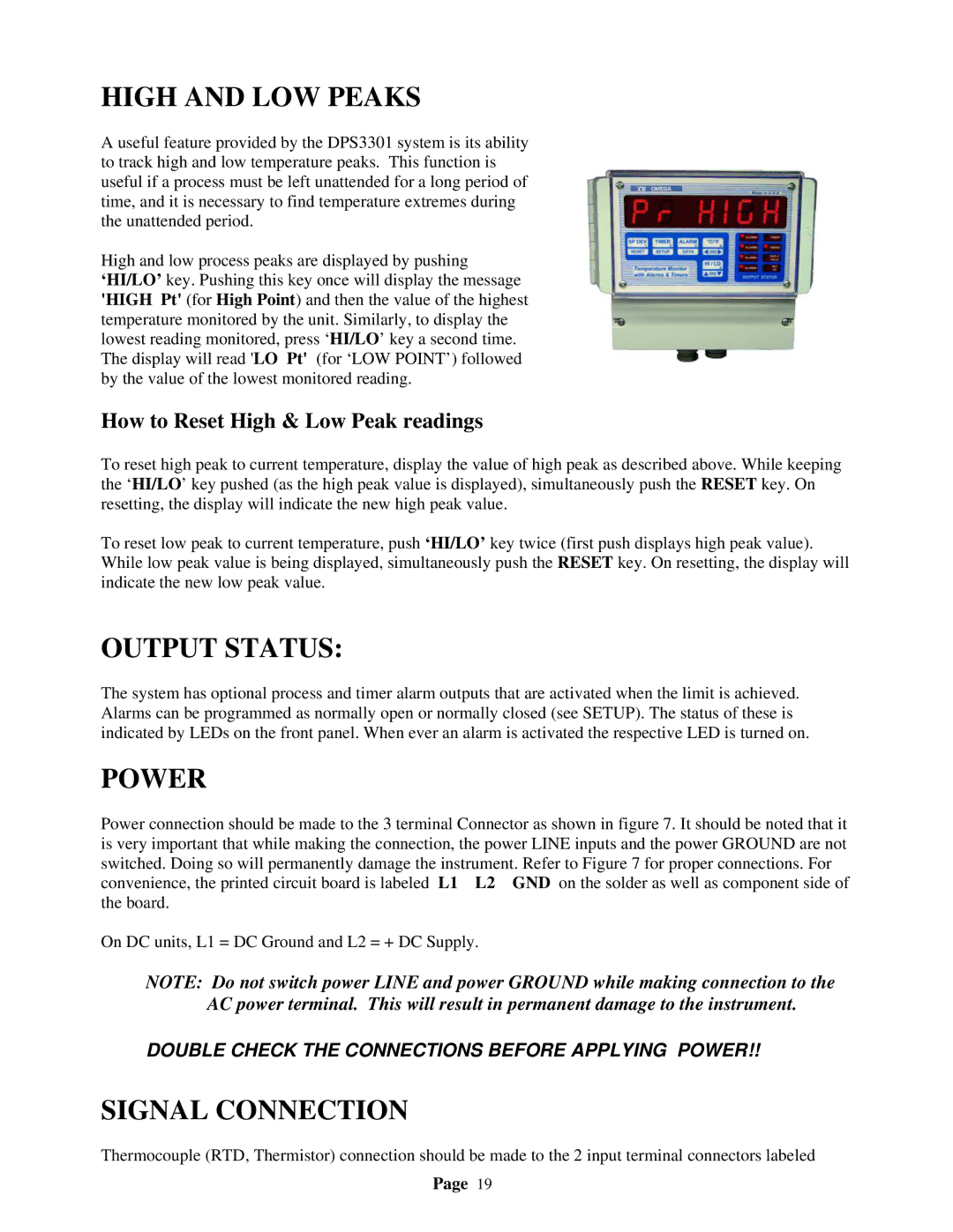
High and low process peaks are displayed by pushing ‘HI/LO’ key. Pushing this key once will display the message 'HIGH Pt' (for High Point) and then the value of the highest temperature monitored by the unit. Similarly, to display the lowest reading monitored, press ‘HI/LO’ key a second time. The display will read 'LO Pt' (for ‘LOW POINT’) followed by the value of the lowest monitored reading.
How to Reset High & Low Peak readings
To reset high peak to current temperature, display the value of high peak as described above. While keeping the ‘HI/LO’ key pushed (as the high peak value is displayed), simultaneously push the RESET key. On resetting, the display will indicate the new high peak value.
To reset low peak to current temperature, push ‘HI/LO’ key twice (first push displays high peak value). While low peak value is being displayed, simultaneously push the RESET key. On resetting, the display will indicate the new low peak value.
OUTPUT STATUS:
The system has optional process and timer alarm outputs that are activated when the limit is achieved. Alarms can be programmed as normally open or normally closed (see SETUP). The status of these is indicated by LEDs on the front panel. When ever an alarm is activated the respective LED is turned on.
POWER
Power connection should be made to the 3 terminal Connector as shown in figure 7. It should be noted that it is very important that while making the connection, the power LINE inputs and the power GROUND are not switched. Doing so will permanently damage the instrument. Refer to Figure 7 for proper connections. For convenience, the printed circuit board is labeled L1 L2 GND on the solder as well as component side of the board.
On DC units, L1 = DC Ground and L2 = + DC Supply.
NOTE: Do not switch power LINE and power GROUND while making connection to the AC power terminal. This will result in permanent damage to the instrument.
DOUBLE CHECK THE CONNECTIONS BEFORE APPLYING POWER!!
SIGNAL CONNECTION
Thermocouple (RTD, Thermistor) connection should be made to the 2 input terminal connectors labeled
Page 19