‘SIGNAL CONNECTOR’ in figure 4. Also indicated are the input signal’s positive and negative polarities for thermocouple connection. These markings are also on the printed circuit board in front of the connector. Care should be taken to connect the positive and negative legs of the signal source to the proper terminals on the connector. A wrong connection will result in incorrect process readings. (No polarity is necessary for RTD or thermistor).
OUTPUT CONNECTOR PIN ASSIGNMENT
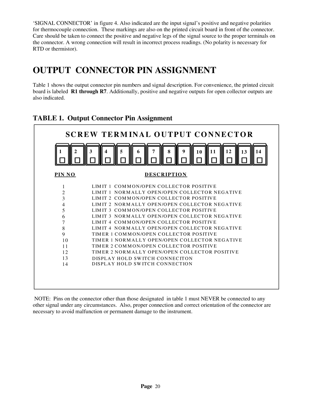
Table 1 shows the output connector pin numbers and signal description. For convenience, the printed circuit board is labeled R1 through R7. Additionally, positive and negative outputs for open collector outputs are also indicated.
TABLE 1. Output Connector Pin Assignment
| SC REW TER M IN AL O U TPUT CO NNEC TO R |
| |||||||||||
1 | 2 | 3 | 4 | 5 | 6 | 7 | 8 | 9 | 10 | 11 | 12 | 13 | 14 |
PIN NO |
|
|
|
| DESCRIPTIO N |
|
|
|
|
| |||
| 1 | LIM IT 1 CO M M O N/O PEN CO LLECT O R PO SIT IV E |
|
|
| ||||||||
| 2 | LIM IT 1 N O R M A LLY O PEN /O PEN CO LLECTO R N EG A TIV E |
| ||||||||||
| 3 | LIM IT 2 CO M M O N/O PEN CO LLECT O R PO SIT IV E |
|
|
| ||||||||
| 4 | LIM IT 2 N O R M A LLY O PEN /O PEN CO LLECTO R N EG A TIV E |
| ||||||||||
| 5 | LIM IT 3 CO M M O N/O PEN CO LLECT O R PO SIT IV E |
|
|
| ||||||||
| 6 | LIM IT 3 N O R M A LLY O PEN /O PEN CO LLECTO R N EG A TIV E |
| ||||||||||
| 7 | LIM IT 4 CO M M O N/O PEN CO LLECT O R PO SIT IV E |
|
|
| ||||||||
| 8 | LIM IT 4 N O R M A LLY O PEN /O PEN CO LLECTO R N EG A TIV E |
| ||||||||||
| 9 | TIM ER 1 CO M M O N /O PEN CO LLECTO R PO SIT IV E |
|
|
| ||||||||
| 10 | TIM ER 1 N O R M A LLY O PEN /O PEN CO LLECTO R N EG A TIV E |
| ||||||||||
| 11 | TIM ER 2 CO M M O N /O PEN CO LLECTO R PO SIT IV E |
|
|
| ||||||||
| 12 | TIM ER 2 N O R M A LLY O PEN /O PEN CO LLECTO R PO SITIV E |
|
| |||||||||
| 13 |
| D ISPLA Y H O L D SW ITCH CO N N EC ITO N |
|
|
|
|
| |||||
| 14 | D ISPLA Y H O L D SW ITCH CO N N ECT IO N |
|
|
|
|
| ||||||
NOTE: Pins on the connector other than those designated in table 1 must NEVER be connected to any other signal under any circumstances. Also, proper connection and correct orientation of the connector are necessary to avoid malfunction or permanent damage to the instrument.
Page 20