2.2 Jumper setup
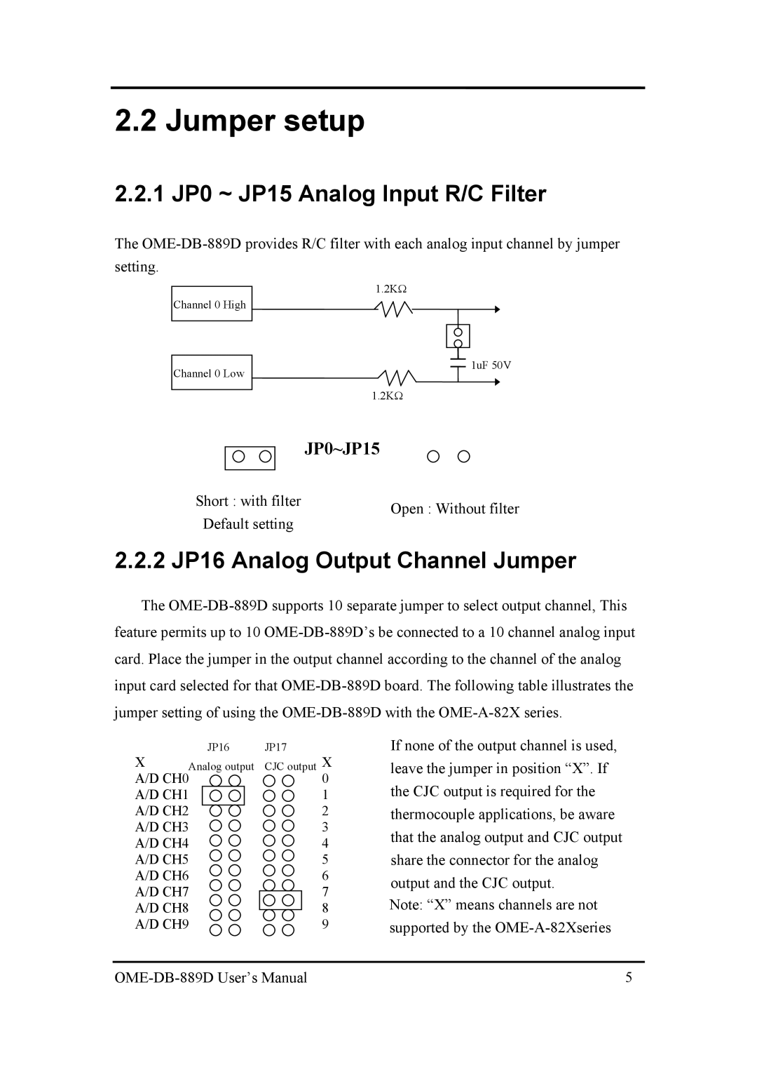
2.2.1 JP0 ~ JP15 Analog Input R/C Filter
The
setting.
Channel 0 High
Channel 0 Low
1.2KΩ
![]() 1uF 50V
1uF 50V
1.2KΩ
JP0~JP15
Short : with filter | Open : Without filter | |
Default setting | ||
|
2.2.2 JP16 Analog Output Channel Jumper
The
| JP16 | JP17 |
X | Analog output | CJC output X |
A/D CH0 | 0 | |
A/D CH1 | 1 | |
A/D CH2 | 2 | |
A/D CH3 | 3 | |
A/D CH4 | 4 | |
A/D CH5 | 5 | |
A/D CH6 | 6 | |
A/D CH7 | 7 | |
A/D CH8 | 8 | |
A/D CH9 | 9 | |
If none of the output channel is used, leave the jumper in position “X”. If the CJC output is required for the thermocouple applications, be aware that the analog output and CJC output share the connector for the analog output and the CJC output.
Note: “X” means channels are not supported by the
| 5 |
