2. Installing
2.1 Layout
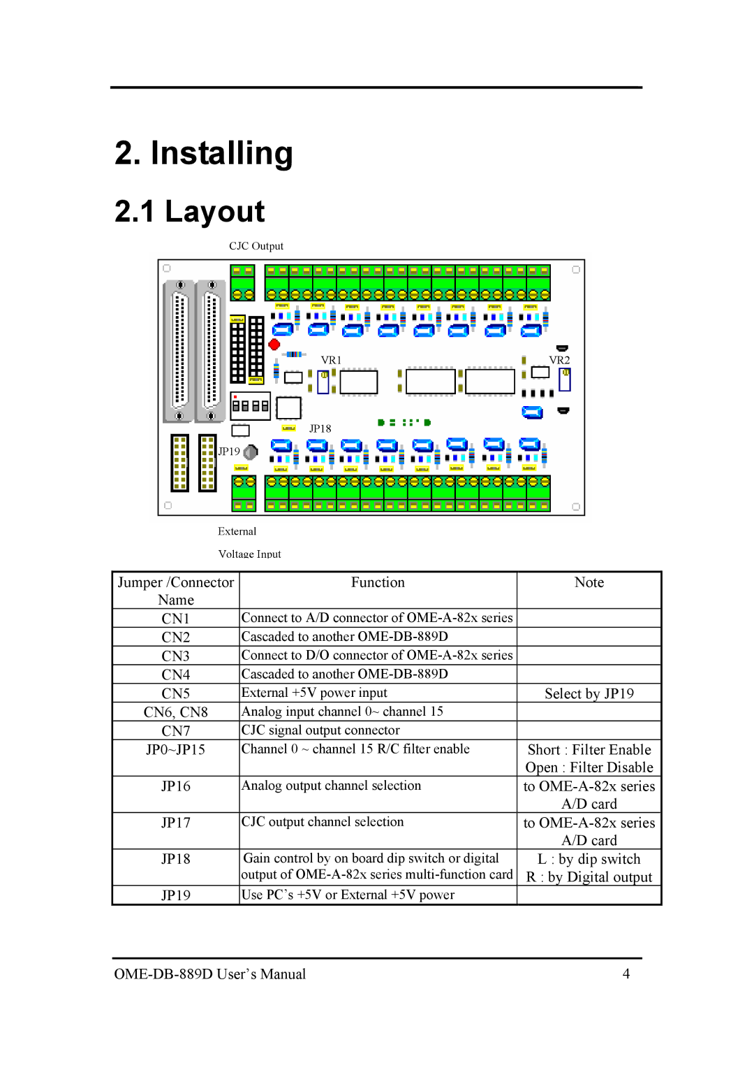
CJC Output
VR1 | VR2 |
JP18
JP19
External
Voltage Input
Jumper /Connector | Function | Note |
Name |
|
|
CN1 | Connect to A/D connector of |
|
CN2 | Cascaded to another |
|
CN3 | Connect to D/O connector of |
|
CN4 | Cascaded to another |
|
CN5 | External +5V power input | Select by JP19 |
CN6, CN8 | Analog input channel 0~ channel 15 |
|
CN7 | CJC signal output connector |
|
JP0~JP15 | Channel 0 ~ channel 15 R/C filter enable | Short : Filter Enable |
|
| Open : Filter Disable |
JP16 | Analog output channel selection | to |
|
| A/D card |
JP17 | CJC output channel selection | to |
|
| A/D card |
JP18 | Gain control by on board dip switch or digital | L : by dip switch |
| output of | R : by Digital output |
JP19 | Use PC’s +5V or External +5V power |
|
| 4 |
