FIG.8

"MP" input board
PT1

SIGNAL INPUT RANGE SELECTION

The "MP" input board for this signal conditioner,
does not have jumpers because it allows only one
signal input (0 to 20 mV). To calibrate the signal
conditioner, follow the adjustment and calibration
procedure.
The user can field adjust the tare using the trim-
mer PT1, located on the "MP" input board. See
Fig. 8.
The signal input 0 to 20 mV will be the standard
range for all orders, unless specified otherwise.

ADJUSTMENT AND CALIBRATION PROCEDURE

To calibrate the signal conditioner, use a calibrator or Vdc source from 0 to 20 mVdc.
1. Open the signal conditioner case. (Fig. 2).
2. Check the "MA" module, if the selected power supply is correct. (Table 1).
3. Connect the calibrator to the signal conditioner terminals 5 - 6.
4. Connect a digital multimeter, to the signal output terminals to be used.
5. Power up the signal conditioner with the correct power supply.
6. Adjust the calibrator until it generates the low signal level (0 Vdc).
7. Turn the "ZERO" trimmer (P1), located on the "ME" input module, until the multimeter
shows the desired low signal output level. (For example: 0 Vdc).
8. Adjust the calibrator until it generates the high signal level.
9. Turn the "GAIN" trimmer (P2), located on the "ME" input module, until the multimeter
shows the desired high output level. (For example: 10 Vdc).
10. Repeat steps 6 to 9, until the two values are correct.

TARE ADJUST PROCEDURE

After the connections between the signal conditioner, load cell and external power supply are
made, connect a multimeter to the output terminals. Do not forget that the load cell must be
free of load.
If the multimeter does not read 0 Vdc or 4 mA, then adjust the trimmer PT1, located on the
"MP" input board.
Check that the high level of the output signal does not change. If it does adjust the GAIN
trimmer (P2) located on the "ME" input module ( see Fig. 7).
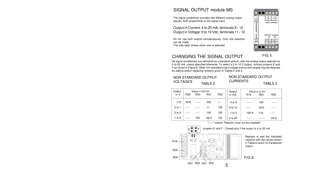
The signal conditioner provides two different analog output
signals, both proportional to the signal input.

Output in Current: 4 to 20 mA, terminals 9 - 10

Output in Voltage: 0 to 10 Vdc, terminals 11 - 12

Do not use both outputs simultaneously. Only one selection
can be made.
The side label shows which one is selected.
SIGNAL OUTPUT module MS
OUTPUTS / SALIDAS
mA Vdc
INPUT / ENTRADA
SUPPLY / ALIMENTACION
3 4 5 6
9 10 11 12
7
1
+
Lo
H i
+--

FIG.5

CHANGING THE SIGNAL OUTPUT
All signal conditioners are delivered as a standard version, with the analog output selected as
4 to 20 mA, unless specified otherwise. To select a 0 to 10 V output, remove jumpers E and
F as shown in Figure 6. Other non-standard output voltage and current ranges may be obtained
by adding and/or replacing resistors given in Tables 2 and 3.
Output Value in for :
in mA. R18 R24 R25
0 to 5 ----- 10 0 -----
0 to 10 ----- 49.9 -----
1 to 5 100 K 124 -----
0 to 20 ----- ------- 24.9
NON STANDARD OUTPUT

CURRENTS

TABLE 2 TABLE 3

NON STANDARD OUTPUT

VOLTAGES

Output Value in Kfor :
in V. R29 R30 R31 R32
±10 49.9 ----- 200 ----
0 to 1 ----- ----- 11 100
0 to 5 ----- ----- 100 100
1 to 5 ----- 100 66 . 5 100
EF
R18
R29
R30
R24 R25 R31 R32

FIG.6

Replace or add the indicated
resistors with the values shown
in Tables 2 and 3 for the desired
output.
5 8
"-----" means "Resistor must not be installed"
Jumpers E and F : Closed only if the output is 4 to 20 mA.