CCT-80, ELECTRICAL FEATURES
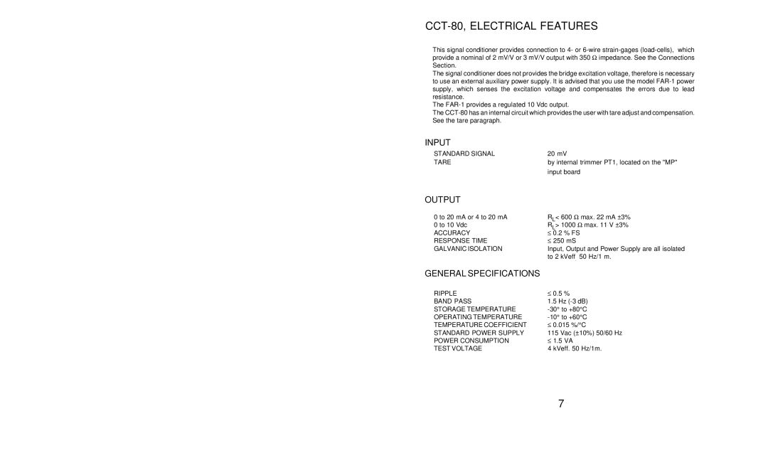
This signal conditioner provides connection to 4- or
The signal conditioner does not provides the bridge excitation voltage, therefore is necessary to use an external auxiliary power supply. It is advised that you use the model
The
The
INPUT
STANDARD SIGNAL | 20 mV |
TARE | by internal trimmer PT1, located on the "MP" |
| input board |
OUTPUT
0 to 20 mA or 4 to 20 mA | RL< 600 Ω max. 22 mA ±3% | |
0 to 10 Vdc | RL> 1000 Ω max. 11 V ±3% | |
ACCURACY | ≤ | 0.2 % FS |
RESPONSE TIME | ≤ | 250 mS |
GALVANIC ISOLATION | Input, Output and Power Supply are all isolated | |
| to 2 kVeff. 50 Hz/1 m. | |
GENERAL SPECIFICATIONS |
|
|
RIPPLE | ≤ | 0.5 % |
BAND PASS | 1.5 Hz | |
STORAGE TEMPERATURE | ||
OPERATING TEMPERATURE | ||
TEMPERATURE COEFFICIENT | ≤ | 0.015 %/°C |
STANDARD POWER SUPPLY | 115 Vac (±10%) 50/60 Hz | |
POWER CONSUMPTION | ≤ | 1.5 VA |
TEST VOLTAGE | 4 kVeff. 50 Hz/1m. | |
7
