SIGNAL INPUT RANGE SELECTION
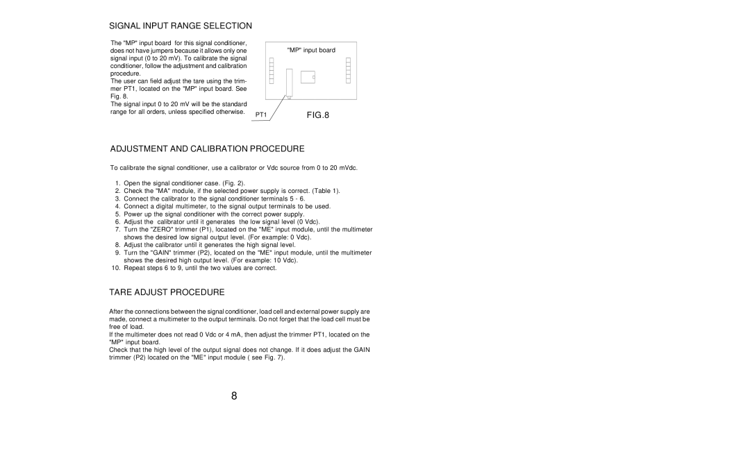
The "MP" input board for this signal conditioner, |
|
|
| "MP" input board | ||||
does not have jumpers because it allows only one |
|
|
| |||||
signal input (0 to 20 mV). To calibrate the signal |
|
|
|
|
|
|
|
|
conditioner, follow the adjustment and calibration |
|
|
|
|
|
|
|
|
|
|
|
|
|
|
|
| |
procedure. |
|
|
|
|
|
|
|
|
|
|
|
|
|
|
|
| |
The user can field adjust the tare using the trim- |
|
|
|
|
|
|
|
|
mer PT1, located on the "MP" input board. See |
|
|
|
|
|
|
|
|
Fig. 8. |
|
|
|
|
|
|
|
|
|
|
|
|
|
|
|
| |
The signal input 0 to 20 mV will be the standard |
|
|
|
|
|
|
|
|
range for all orders, unless specified otherwise. | PT1 |
|
|
| FIG.8 | |||
|
|
|
| |||||
ADJUSTMENT AND CALIBRATION PROCEDURE
To calibrate the signal conditioner, use a calibrator or Vdc source from 0 to 20 mVdc.
1.Open the signal conditioner case. (Fig. 2).
2.Check the "MA" module, if the selected power supply is correct. (Table 1).
3.Connect the calibrator to the signal conditioner terminals 5 - 6.
4.Connect a digital multimeter, to the signal output terminals to be used.
5.Power up the signal conditioner with the correct power supply.
6.Adjust the calibrator until it generates the low signal level (0 Vdc).
7.Turn the "ZERO" trimmer (P1), located on the "ME" input module, until the multimeter shows the desired low signal output level. (For example: 0 Vdc).
8.Adjust the calibrator until it generates the high signal level.
9.Turn the "GAIN" trimmer (P2), located on the "ME" input module, until the multimeter shows the desired high output level. (For example: 10 Vdc).
10.Repeat steps 6 to 9, until the two values are correct.
TARE ADJUST PROCEDURE
After the connections between the signal conditioner, load cell and external power supply are made, connect a multimeter to the output terminals. Do not forget that the load cell must be free of load.
If the multimeter does not read 0 Vdc or 4 mA, then adjust the trimmer PT1, located on the "MP" input board.
Check that the high level of the output signal does not change. If it does adjust the GAIN trimmer (P2) located on the "ME" input module ( see Fig. 7).
8