The channel LEDs are connected in series with the output current so that they will light only as an indication of a closed current loop.
Note: After every power on, the unit is reset and the initialized default output currents are according to the SW6 setting (see para #5.2).
In the parallel control mode, internal
11. DRA-DCC-8 CALIBRATION
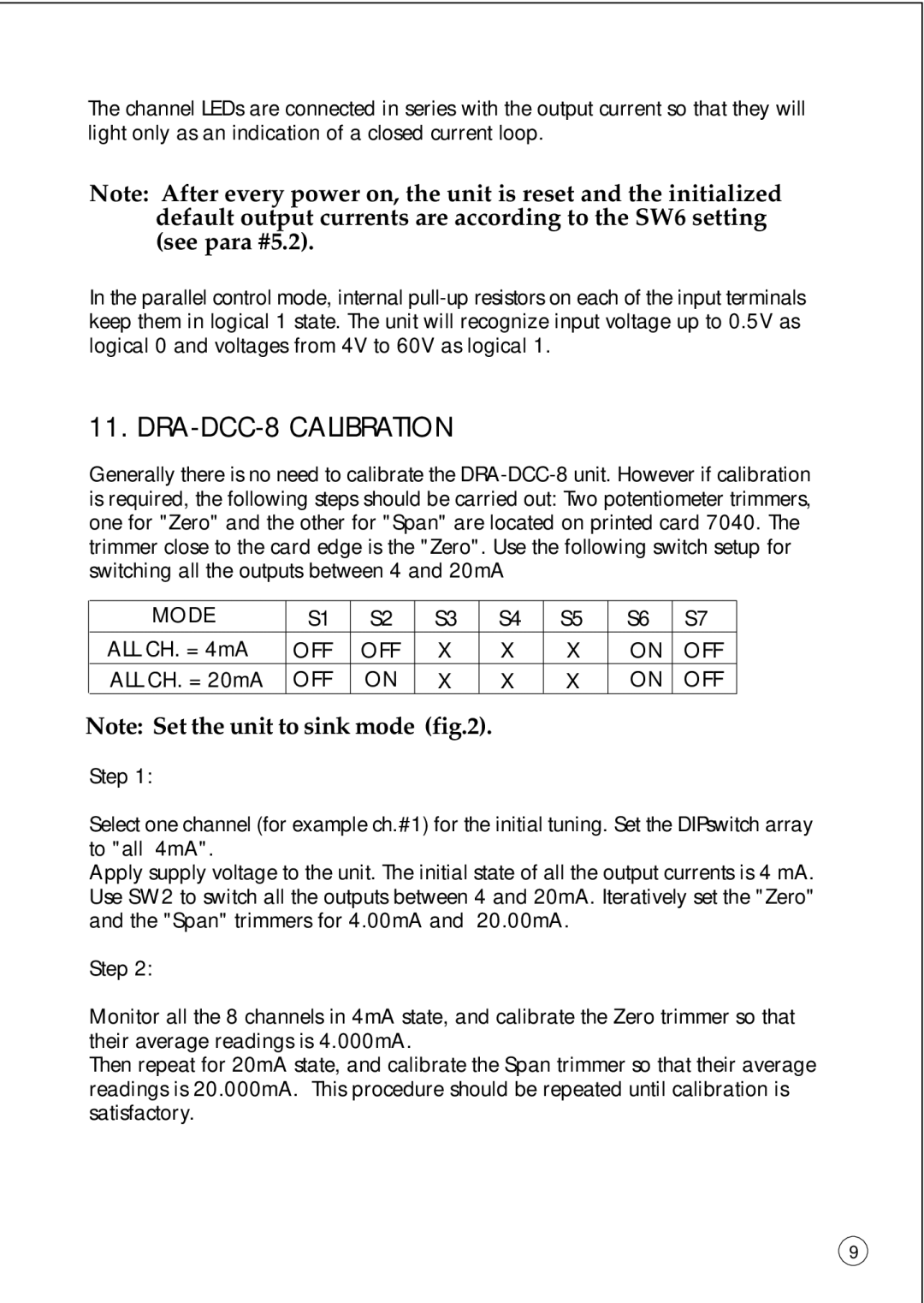
Generally there is no need to calibrate the
MODE | S1 | S2 | S3 | S4 | S5 | S6 | S7 |
ALL CH. = 4mA | OFF | OFF | X | X | X | ON | OFF |
ALL CH. = 20mA | OFF | ON | X | X | X | ON | OFF |
Note: Set the unit to sink mode (fig.2).
Step 1:
Select one channel (for example ch.#1) for the initial tuning. Set the DIPswitch array to "all 4mA".
Apply supply voltage to the unit. The initial state of all the output currents is 4 mA. Use SW2 to switch all the outputs between 4 and 20mA. Iteratively set the "Zero" and the "Span" trimmers for 4.00mA and 20.00mA.
Step 2:
Monitor all the 8 channels in 4mA state, and calibrate the Zero trimmer so that their average readings is 4.000mA.
Then repeat for 20mA state, and calibrate the Span trimmer so that their average readings is 20.000mA. This procedure should be repeated until calibration is satisfactory.
9
