Serial Control Mode
| BAUD RATE (BPS) | S1 |
| S2 | S3 | S4 | S5 |
|
| S6 |
| S7 | ||
300 | OFF |
| OFF |
|
|
|
|
| ON | |||||
| 4800 | ON |
| OFF | UNIT ID CODE |
|
|
|
| ON | ||||
9600 | OFF |
| ON |
| ON | |||||||||
|
|
|
|
| ||||||||||
| 19200 | ON |
| ON |
|
|
|
|
|
|
| ON | ||
SW5 MSB |
|
|
| Self Test Mode |
|
|
|
|
|
| ||||
|
|
|
|
|
|
|
|
|
|
| ||||
|
|
|
|
|
|
|
|
|
|
|
|
|
|
|
| MODE |
|
| S1 |
| S2 | S3 | S4 |
| S5 | S6 |
| S7 | |
| SELF TEST#1 |
|
| ON |
| OFF |
| X |
|
| X |
| OFF | |
| SELF TEST#2 |
| OFF |
| ON |
| X |
|
| * |
| OFF | ||
| SELF TEST#3 |
|
| ON |
| ON |
| X |
|
| * |
| OFF | |
* according to para #5.2
6. PARALLEL CONTROL MODE
MODE | S1 | S2 | S3 | S4 | S5 | S6 | S7 |
PARALLEL MODE | OFF | OFF |
| X |
| * | OFF |
* according to para #5.2
In the parallel control mode, the
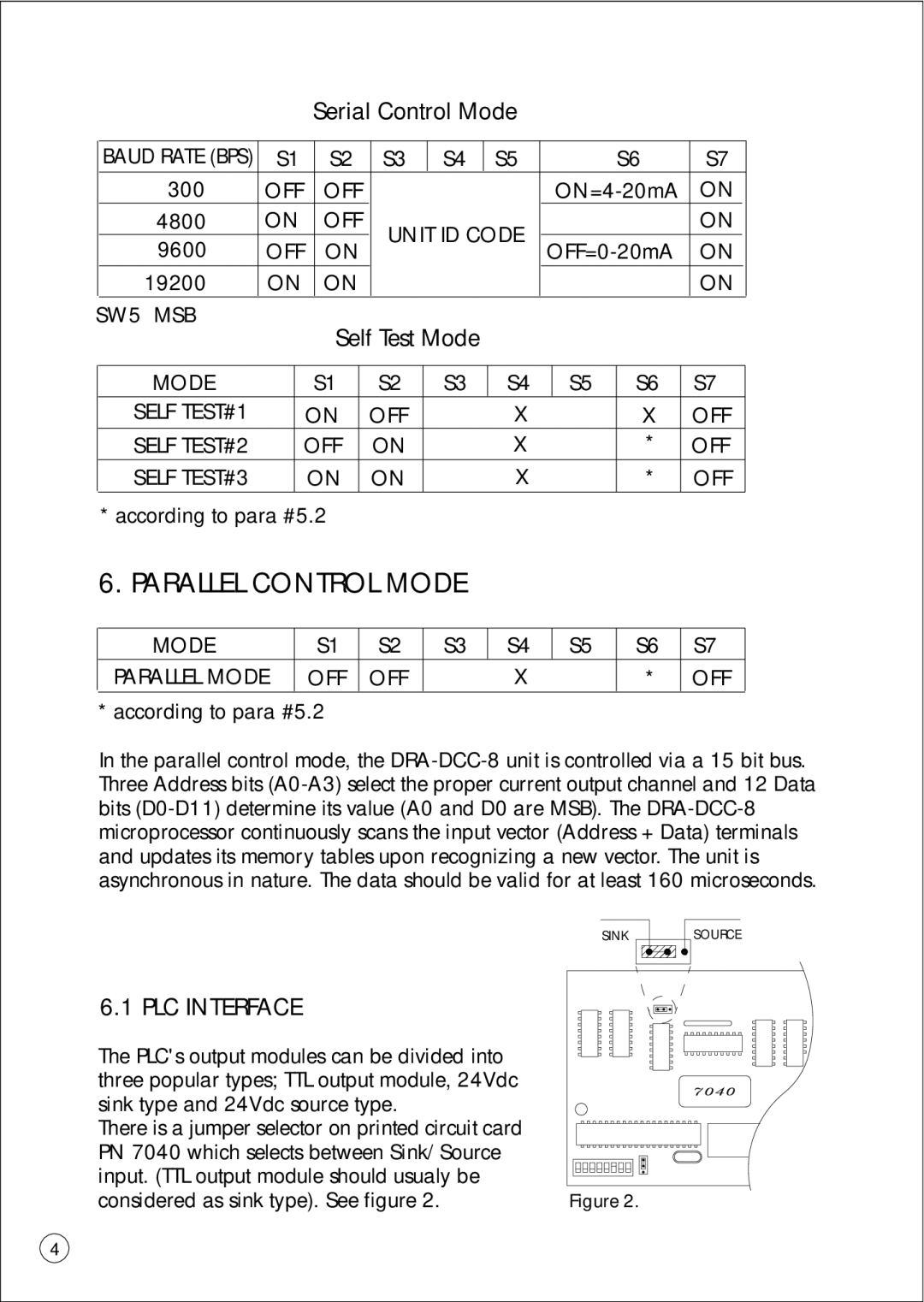
SINKSOURCE
6.1 PLC INTERFACE |
|
The PLC's output modules can be divided into |
|
three popular types; TTL output module, 24Vdc |
|
sink type and 24Vdc source type. |
|
There is a jumper selector on printed circuit card |
|
PN 7040 which selects between Sink/Source |
|
input. (TTL output module should usualy be |
|
considered as sink type). See figure 2. | Figure 2. |
4