4. SUPPLY VOLTAGE
The
Vmin = 8 + Rload(Ω ) * 0.02
where:
Vmin is the minimum required supply voltage.
Rload(Ω ) is the maximum output load including the leads resistance.
Note: If Vmin turns to be less than 15V, the minimum required voltage should be 15 Vdc.
5. MODES OF OPERATION
The
![]()
![]() Parallel control mode
Parallel control mode
![]() Serial control mode
Serial control mode
![]() Self test mode
Self test mode
5.1 0-20 OR 4-20mA OUTPUT CURRENT MODE
Two current output spans are available:
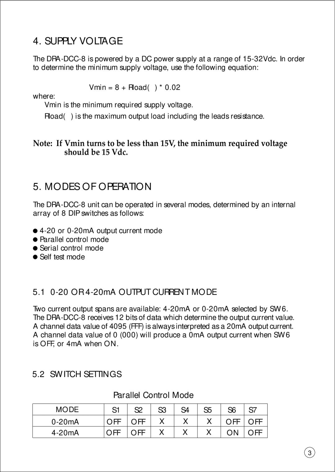
5.2 SWITCH SETTINGS
Parallel Control Mode
MODE | S1 | S2 | S3 | S4 | S5 | S6 | S7 |
OFF | OFF | X | X | X | OFF | OFF | |
OFF | OFF | X | X | X | ON | OFF |
3