6.2 THE "E" (ENABLE) TERMINAL
For E="1" the unit is enabled, which means that all input vectors are received and the output is updated. When E="0" the unit ignores any new input vector. The E terminal is recommended to be used as a strobe for parallel data which has a long setup time. In this case the following sequence is recommended: prior to applying a new vector, the E terminal should be set to logical 0 (inhibit state), then the new input vector should be imposed. Once the new data is set, the E terminal should be pulsed.
The E terminal is also used for multidrop configuration. The 15 bit vectors are applied to the units in parallel and the selection is carried out by controlling the "E" inputs.
7. SERIAL CONTROL MODE
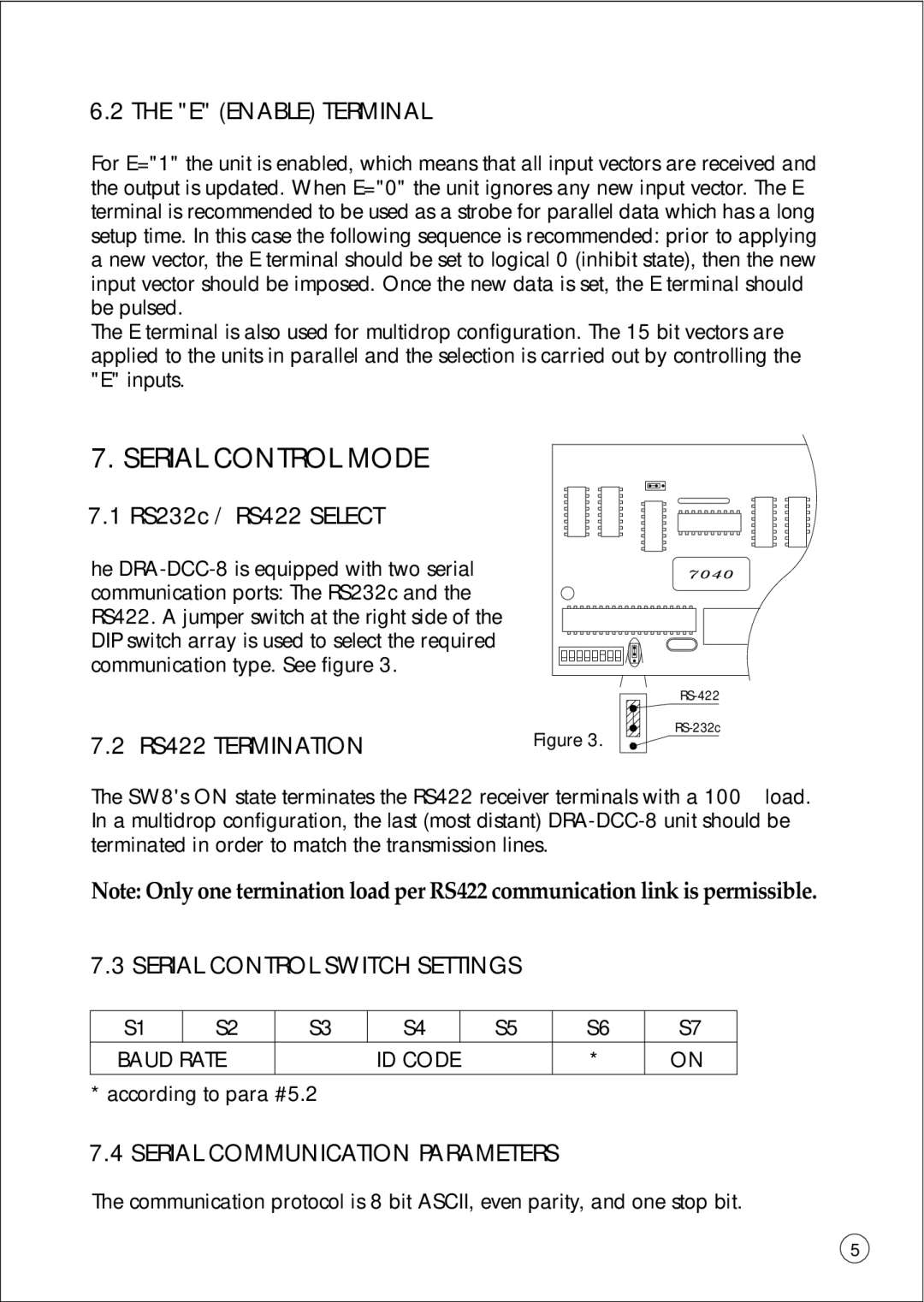
7.1 RS232c / RS422 SELECT
he
7.2 RS422 TERMINATION
Figure 3.
The SW8's ON state terminates the RS422 receiver terminals with a 100W load. In a multidrop configuration, the last (most distant)
Note: Only one termination load per RS422 communication link is permissible.
7.3 SERIAL CONTROL SWITCH SETTINGS
S1 | S2 | S3 | S4 | S5 | S6 | S7 |
BAUD RATE |
| ID CODE |
| * | ON | |
* according to para #5.2
7.4 SERIAL COMMUNICATION PARAMETERS
The communication protocol is 8 bit ASCII, even parity, and one stop bit.
5
