9.- TEMPERATURE RANGES
9.1.- MODEL M1, M2 & M3. RTD SENSOR (PT-100)
MODEL | TEMPERATURE |
| ACCURACY | RESOLUTION | MAXIMUM |
| RANGE |
| (±1 COUNT) |
| COMPENSATION |
|
|
|
|
| |
M1 | - 100.0 to + 650.0 °C | ± 0.4 % | 0.1 °C |
| |
|
|
|
|
| 10Ω |
M2 | °F | ± 0.4 % | 1 °F | ||
|
|
|
|
|
|
M3 | - 200.0 to 999.9 | °F | ± 0.2 % | 0.1 °F |
|
|
|
|
|
|
|
Allowable error in negative range due to the lead wire resistance : 0.2°C/Ω or 0.4°F/Ω
9.2.- MODELS: J1,J2,K1,K2,T1,T2, E1,E2,S1,S2,R1,R2 & L1. THERMOCOUPLE SENSORS
MODEL | TEMPERATURE | ACCURACY |
| MODEL | TEMPERATURE | ACCURACY | RESOLUTION | AMBIENT TEMP. | ||||||
| RANGE | ± 1 count |
|
|
| RANGE | ± 1 count |
| COMPENSATION | |||||
|
|
|
|
|
|
|
|
|
|
|
|
|
|
|
J 1 | - 50 to + 600°C | ± 0.5 % |
| J 2 | - 40 to | 1000°F | ± 0.5 % |
| 1°C / 1°F |
| ||||
|
|
|
|
|
|
|
|
|
|
|
|
|
|
|
K1 | 0 to + 1250°C | ± 0.5 % |
| K2 | 32 to | 2250°F | ± 0.5 % |
| 1°C / 1°F |
| ||||
|
|
|
|
|
|
|
|
|
|
|
|
|
|
|
T1 | - 50 to + 400°C | ± 0.5 % |
| T2 | - 40 to | 750°F | ± 1 % |
| 1°C / 1°F | ALL MODELS | ||||
|
|
|
|
|
|
|
|
|
|
|
|
|
| |
|
|
|
|
|
|
|
|
|
|
|
|
|
| |
E1 | 0 to + 650°C | ± 0.2 % |
| E2 | 32 to 1200°F | ± 0.3 % |
| 1°C / 1°F | 0°C to + 50°C | |||||
|
|
|
|
|
|
|
|
|
|
|
|
|
| 32°F to 122°F |
S1 | + 970 to + 1750°C | ± 0.1 % |
| S2 | 1775 to | 3150°F | ± 0.2 % |
| 1°C / 1°F | |||||
|
|
| ||||||||||||
|
|
|
|
|
|
|
|
|
|
|
|
|
|
|
R1 | + 1000 to + 1750°C | ± 0.2 % |
| R2 | 1850 to | 3150°F | ± 0.3 % |
| 1°C / 1°F |
| ||||
|
|
|
|
|
|
|
|
|
|
|
|
|
|
|
L1 | - 50 to + 600°C | ± 0.5 % |
|
|
|
|
|
|
|
|
|
| 1°C |
|
|
|
|
|
|
|
|
|
|
|
| ||||
|
|
|
|
|
|
|
|
|
|
|
|
|
|
|
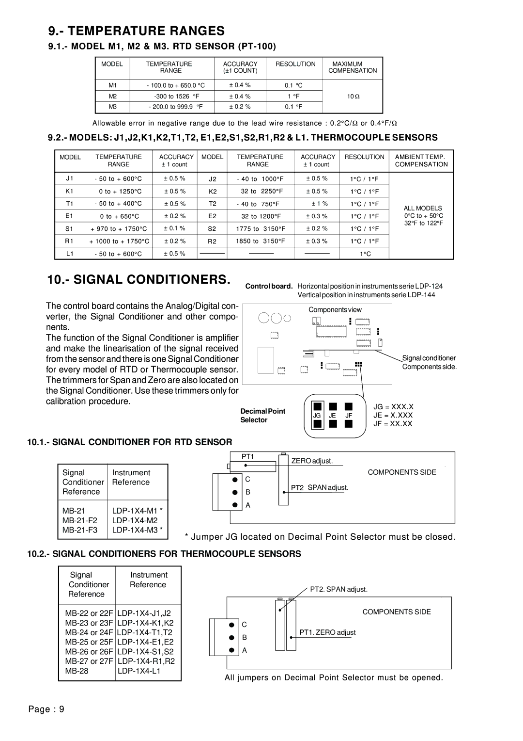
10.- SIGNAL CONDITIONERS.
Control board. Horizontal position in instruments serie
Vertical position in instruments serie
The control board contains the Analog/Digital con- verter, the Signal Conditioner and other compo- nents.
The function of the Signal Conditioner is amplifier and make the linearisation of the signal received from the sensor and there is one Signal Conditioner for every model of RTD or Thermocouple sensor. The trimmers for Span and Zero are also located on the Signal Conditioner. Use these trimmers only for calibration procedure.
Components view
![]() Signal conditioner
Signal conditioner
Components side.
Decimal Point |
|
|
|
|
|
|
| JG = XXX.X | |
|
|
|
|
|
|
| |||
JG | JE JF | JE = X.XXX | |||||||
Selector | |||||||||
|
|
|
|
|
|
| JF = XX.XX | ||
|
|
|
|
|
|
| |||
|
|
|
|
|
|
|
| ||
|
|
|
|
|
|
|
|
| |
10.1.- SIGNAL CONDITIONER FOR RTD SENSOR
Signal | Instrument |
Conditioner | Reference |
PT1
C
ZERO adjust.
COMPONENTS SIDE
Reference |
|
|
|
B A
PT2 SPAN adjust.
* Jumper JG located on Decimal Point Selector must be closed.
10.2.- SIGNAL CONDITIONERS FOR THERMOCOUPLE SENSORS
Signal | Instrument |
Conditioner | Reference |
Reference |
|
PT2. SPAN adjust.
COMPONENTS SIDE
C
PT1. ZERO adjust
B
A
All jumpers on Decimal Point Selector must be opened.
Page : 9