INSTALLATION - Sensor
When installed in accordance with this installation proce- dure, the sensor is suitable for use in Class I, Division 1, Groups C and D.
1.With protective shield attached, sensor can be pulled through interstitial space of
2.Sensor may be installed in horizontal or vertical positions, only.
3.Do not install sensor close to infrared sources.
4.Prism surface must be at least 2" from any reflective surfaces.
5.Connect
( ) black lead.
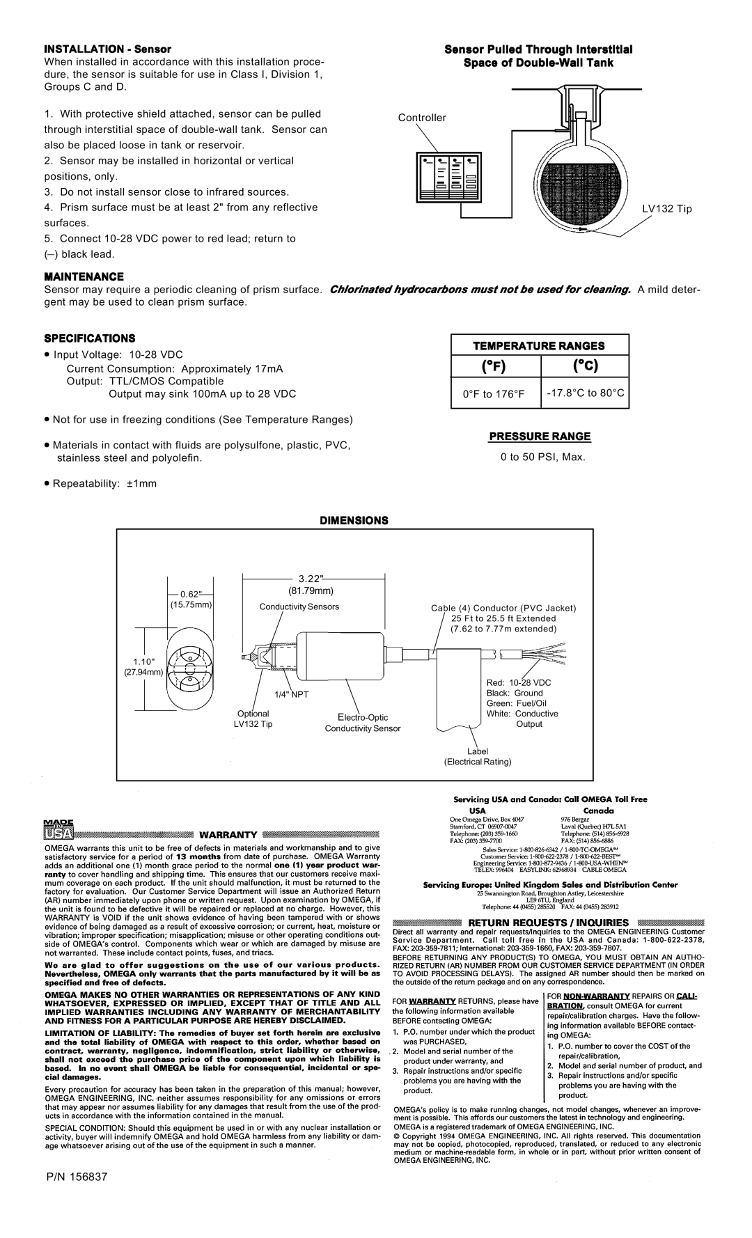
Sensor Pulled Through Interstitial
Space of
Controller
LV132 Tip
MAINTENANCE
Sensor may require a periodic cleaning of prism surface. Chlorinated hydrocarbons must not be used for cleaning. A mild deter- gent may be used to clean prism surface.
SPECIFICATIONS | TEMPERATURE RANGES | |||
• Input Voltage: | ||||
|
| |||
(°F) | (°C) | |||
Current Consumption: Approximately 17mA | ||||
Output: TTL/CMOS Compatible |
|
|
| |
|
| |||
Output may sink 100mA up to 28 VDC | 0°F to 176°F | |||
|
|
|
| |
•Not for use in freezing conditions (See Temperature Ranges)
• | Materials in contact with fluids are polysulfone, plastic, PVC, | PRESSURE RANGE | |
0 to 50 PSI, Max. | |||
| stainless steel and polyolefin. | ||
• | Repeatability: ±1mm |
|
DIMENSIONS
0.62"
(15.75mm)
1.10"
(27.94mm)
|
|
| 3.22" |
|
|
|
|
|
|
|
|
|
|
| |
|
| (81.79mm) |
|
|
| ||
| Conductivity Sensors |
|
| Cable (4) Conductor (PVC Jacket) | |||
|
|
|
|
|
|
| 25 Ft to 25.5 ft Extended |
|
|
|
|
|
|
| (7.62 to 7.77m extended) |
|
|
|
|
|
| ||
|
|
|
|
|
|
| Red: |
|
|
|
|
|
|
| |
|
|
|
|
|
|
| |
|
|
|
|
|
|
| |
|
|
|
|
|
|
| |
|
| 1/4" NPT |
| Black: Ground | |||
|
|
|
|
|
|
| Green: Fuel/Oil |
Optional |
|
|
| White: Conductive | |||
LV132 Tip |
|
|
| Output | |||
|
| Conductivity Sensor |
| ||||
|
|
|
|
|
| ||
Label
(Electrical Rating)
P/N 156837