Abbreviated Transmission (

=

)

BYTE DESCRIPTION

1-12 12 byte data field, 6 bytes for number, up to 3 bytes for decimal points.

13<CR> (Carriage return)

14<LF> (Line feed)

15<SP> (Space)

16<CR> (Carriage return)

17<LF> (Line feed)

These characters only appear in the last line of a block print.

The abbreviated response suppresses the address and register mnemonics, leaving only the numeric part of the response.

Note: Transmissions are formatted to match the way the parameter is displayed. This includes setpoints.

Example: SP1 assigned to RTC. RTC format = 12:00 P. SP1 printout = 12:00 P.

Meter Response Examples:

1. Address = 17, full field response, Cycle Counter = 875

17 CNT

875 <CR><LF>

2. Address = 0, full field response, Setpoint 2 = 250.5

SP2 250.5<CR><LF>

3.Address = 0, abbreviated response, Setpoint 2 = 250, last line of block print 250<CR><LF><SP><CR><LF>

Auto/Manual Mode Register (MMR) ID: U

This register sets the controlling mode for the outputs. In Auto Mode (0) the meter controls the setpoint output. In Manual Mode (1) the outputs are defined by the registers SOR. When transferring from auto mode to manual mode, the meter holds the last output value (until the register is changed by a write). Each output may be independently changed to auto or manual. In a write command string (VU), any character besides 0 or 1 in a field will not change the corresponding output mode.

U abcd

d = SP4 c = SP3 b = SP2 a = SP1

Example: VU0011 places SP3 and SP4 in manual.

Setpoint Output Register (SOR) ID: X

This register is used to view or change the states of the setpoint outputs. Reading from this register (TX) will show the present state of all the setpoint outputs. A “0” in the setpoint location means the output is inactive and a “1” means the output is active. The output logic parameter in Module 6 will affect the active logic state.

X abcd

d = SP4 c = SP3 b = SP2 a = SP1

In Automatic Mode, the meter controls the setpoint output state. In Manual Mode, writing to this register (VX) will change the output state. Sending any character besides 0 or 1 in a field or if the corresponding output was not first in manual mode, the corresponding output value will not change.

Example: VX10* will result in output 1 active and output 2 inactive.

COMMAND RESPONSE TIME

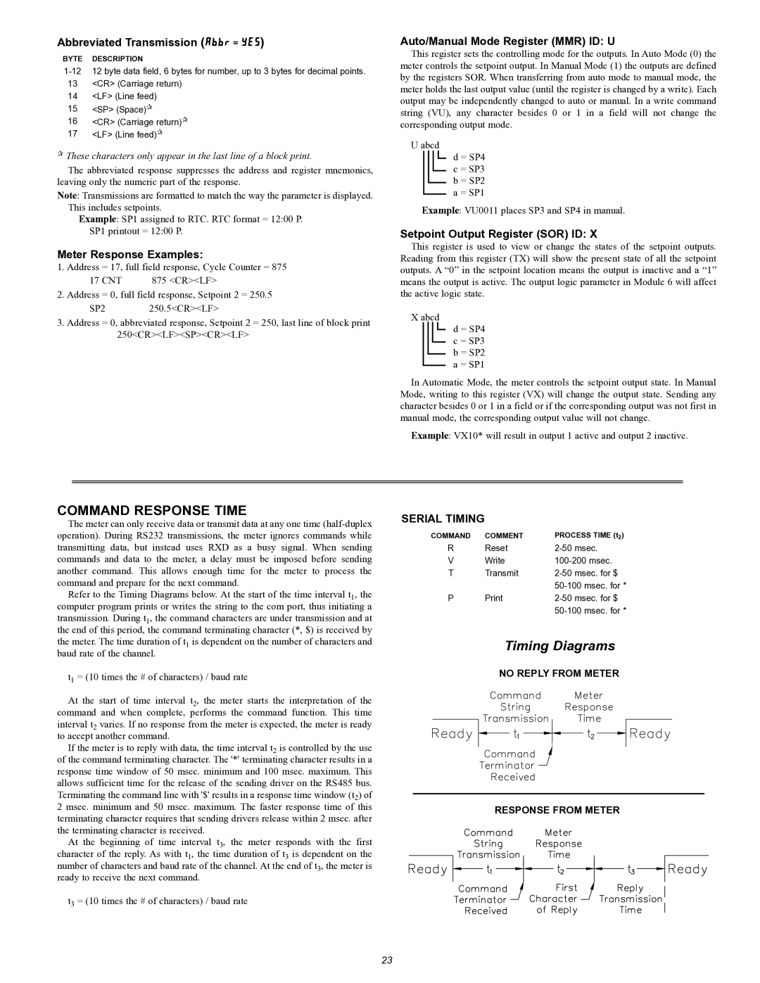
The meter can only receive data or transmit data at any one time (half-duplex operation). During RS232 transmissions, the meter ignores commands while transmitting data, but instead uses RXD as a busy signal. When sending commands and data to the meter, a delay must be imposed before sending another command. This allows enough time for the meter to process the command and prepare for the next command.

Refer to the Timing Diagrams below. At the start of the time interval t1, the computer program prints or writes the string to the com port, thus initiating a transmission. During t1, the command characters are under transmission and at the end of this period, the command terminating character (*, $) is received by the meter. The time duration of t1 is dependent on the number of characters and baud rate of the channel.

t1 = (10 times the # of characters) / baud rate

At the start of time interval t2, the meter starts the interpretation of the command and when complete, performs the command function. This time interval t2 varies. If no response from the meter is expected, the meter is ready to accept another command.

If the meter is to reply with data, the time interval t2 is controlled by the use of the command terminating character. The '*' terminating character results in a response time window of 50 msec. minimum and 100 msec. maximum. This allows sufficient time for the release of the sending driver on the RS485 bus. Terminating the command line with '$' results in a response time window (t2) of 2 msec. minimum and 50 msec. maximum. The faster response time of this terminating character requires that sending drivers release within 2 msec. after the terminating character is received.

At the beginning of time interval t3, the meter responds with the first character of the reply. As with t1, the time duration of t3 is dependent on the number of characters and baud rate of the channel. At the end of t3, the meter is ready to receive the next command.

t3 = (10 times the # of characters) / baud rate

SERIAL TIMING

COMMAND

COMMENT

PROCESS TIME (t2)

R

Reset

2-50 msec.

V

Write

100-200 msec.

T

Transmit

2-50 msec. for $


50-100 msec. for *

P

Print

2-50 msec. for $


50-100 msec. for *

Timing Diagrams

NO REPLY FROM METER

RESPONSE FROM METER

23

Page 23
Image 23
Omega Vehicle Security PTC900 manual Abbreviated Transmission, Meter Response Examples, Auto/Manual Mode Register MMR ID U

PTC900 specifications

The Omega Vehicle Security PTC900 is a sophisticated vehicle security system designed to provide comprehensive protection against theft and unauthorized access. This cutting-edge technology integrates advanced features and a robust design to ensure peace of mind for vehicle owners.

One of the standout characteristics of the PTC900 is its state-of-the-art immobilizer technology. The system incorporates a unique electronic key code that prevents the engine from starting unless the authorized key is present. This feature significantly deters potential thieves, making it exceedingly difficult to operate the vehicle without the proper authorization.

The PTC900 is equipped with a dual-stage shock sensor that detects both minor and significant impacts. When a disturbance is detected, the system emits a loud alarm, drawing attention and potentially scaring off intruders. This sensor capability allows for a tailored response to various threats, enhancing security without unnecessary disruptions from harmless movements.

Additionally, the Omega Vehicle Security system includes a remote keyless entry feature, allowing users to lock and unlock their vehicles from a distance conveniently. This technology not only provides ease of use but also reinforces the security system by eliminating the need for traditional keys that can be copied or misused.

Another remarkable aspect of the PTC900 is its user-friendly interface. The intuitive control panel enables quick adjustments and customizations to various security settings, allowing users to tailor the system to their specific needs. With clear indicators for system status, users can easily monitor their vehicle’s security at a glance.

The reliability of the Omega Vehicle Security system is further enhanced by its weather-resistant construction, ensuring durability under various environmental conditions. The compact design allows for seamless integration into different vehicle types without compromising aesthetics or functionality.

For those seeking enhanced peace of mind, the PTC900 also offers optional GPS tracking capabilities. This feature enables vehicle owners to monitor their vehicle's location in real time, providing an additional layer of security against theft. If the vehicle is stolen, owners can quickly share location data with law enforcement, increasing the likelihood of recovery.

In conclusion, the Omega Vehicle Security PTC900 stands out as a premium solution in vehicle protection. With its advanced immobilizer technology, dual-stage shock sensor, remote keyless entry, user-friendly features, and optional GPS tracking, it provides comprehensive security, ensuring that vehicle owners can enjoy their investments without fear.