4 | Omnitron Systems Technology, Inc. |
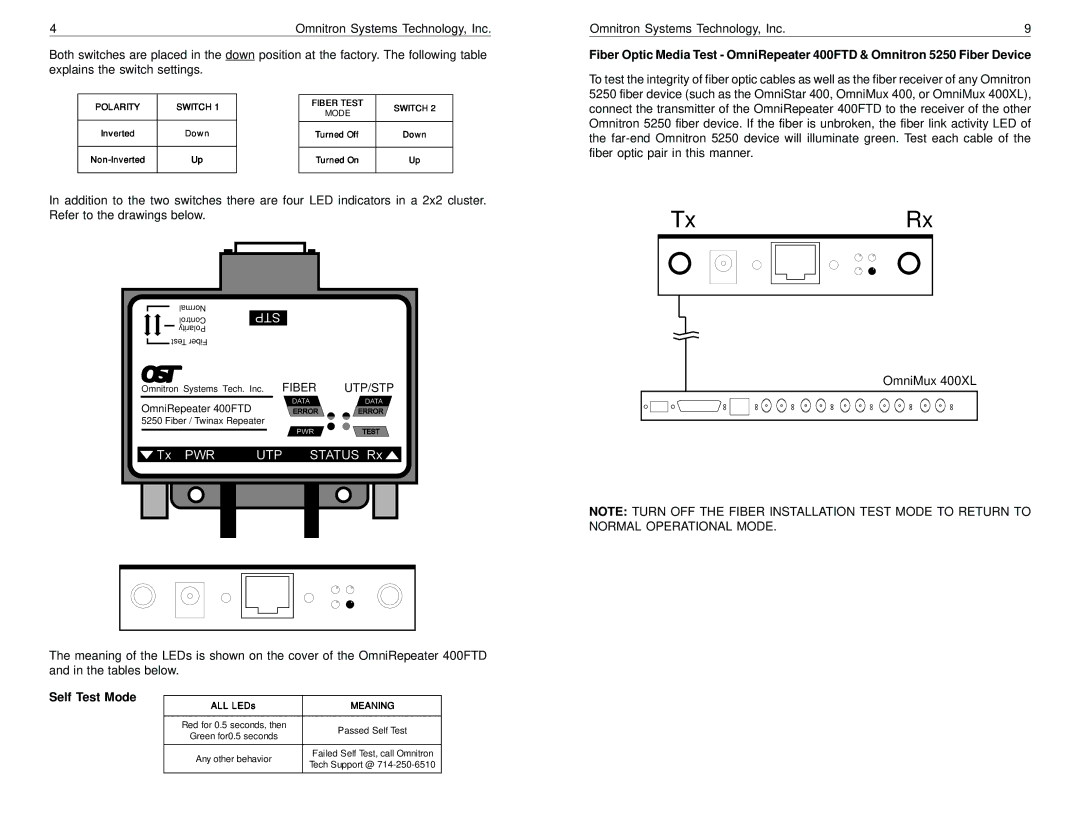
Both switches are placed in the down position at the factory. The following table explains the switch settings.
POLARITY | SWITCH 1 |
| FIBER TEST | SWITCH 2 |
| MODE | |||
|
|
|
| |
Inverted | Down |
|
|
|
| Turned Off | Down | ||
|
|
|
|
|
Up |
| Turned On | Up | |
|
|
|
|
|
In addition to the two switches there are four LED indicators in a 2x2 cluster. Refer to the drawings below.
Normal |
|
|
Control |
|
|
Polarity |
|
|
Test Fiber |
|
|
Omnitron Systems Tech. Inc. | FIBER | UTP/STP |
OmniRepeater 400FTD |
|
|
5250 Fiber / Twinax Repeater |
|
|
The meaning of the LEDs is shown on the cover of the OmniRepeater 400FTD and in the tables below.
Self Test Mode
ALL LEDs | MEANING | |
|
| |
Red for 0.5 seconds, then | Passed Self Test | |
Green for0.5 seconds | ||
| ||
|
| |
Any other behavior | Failed Self Test, call Omnitron | |
Tech Support @ | ||
|
Omnitron Systems Technology, Inc. | 9 |
Fiber Optic Media Test - OmniRepeater 400FTD & Omnitron 5250 Fiber Device
To test the integrity of fiber optic cables as well as the fiber receiver of any Omnitron 5250 fiber device (such as the OmniStar 400, OmniMux 400, or OmniMux 400XL), connect the transmitter of the OmniRepeater 400FTD to the receiver of the other Omnitron 5250 fiber device. If the fiber is unbroken, the fiber link activity LED of the
Tx |
|
|
|
|
|
|
| Rx | ||||
|
|
|
|
|
|
|
|
|
|
|
|
|
|
|
|
|
|
|
|
|
|
|
|
|
|
|
|
|
|
|
|
|
|
|
|
|
|
|
|
|
|
|
|
|
|
|
|
|
|
|
|
|
|
|
|
|
|
|
|
|
|
|
|
|
|
|
|
|
|
|
|
|
|
|
|
|
|
|
|
|
|
|
|
|
|
|
|
|
|
|
|
|
|
|
|
|
|
|
|
|
|
|
|
|
|
|
|
|
|
|
|
|
|
|
|
|
OmniMux 400XL
NOTE: TURN OFF THE FIBER INSTALLATION TEST MODE TO RETURN TO NORMAL OPERATIONAL MODE.
