6 | Omnitron Systems Technology, Inc. |
Run-time Activity & Error Monitoring
During normal operation the Link and Port LEDs provide continuous diagnostic information. These LEDs detect and display true link and port activity and data parity errors. This is accomplished by individual port monitoring and searching for legal frame header patterns.
Upon detection of a valid frame pattern, a green LED indicator displays the detected activity. This feature assists in installation and in the selection of the correct polarity baluns and/or setting the polarity of the switch.
The data is analyzed for correct parity and the detection of parity error is indicated by a red LED. This feature facilitates the continuous monitoring of signal and line quality.
INSTALLATION
Unpacking
a.Visual Inspection – Before unpacking, a visual inspection should be conducted in order to detect any physical damage to the equipment. Any evidence of the damage should be noted and reported immediately.
b.Unpacking – Place shipping container on a flat surface, cut straps or tape, open top. Take out each item carefully and place securely on a clean flat surface. Return all packing material into a container (foam, boxes, etc.), close and store away for future reuse.
c.Inspection – Inspect each item for any apparent damage, any evidence of damage should be noted and reported immediately.
d.Content – Review the content; the following items should be included:
(a)OmniRepeater 400FTD Unit
(b)One (1) Power Supply Module
(c)User Manual (this document)
e.Please note any missing items or discrepancies and report them immediately.
SITE REQUIREMENTS
Power
A power outlet 115 Volts/60 Hz (230 Volts/50 Hz) should be available within 5 ft. of the unit.
MODEL | POWER OUTLET |
|
|
110 Volt - 60 Hz | |
|
|
220 Volt - 50 Hz | |
|
|
110 Volt - 60 Hz | |
|
|
220 Volt - 50 Hz | |
|
|
Omnitron Systems Technology, Inc. | 7 |
CONFIGURATION
Normal
a. Turn off the terminal or printer being attached.
b. Attach the terminal or printer with the appropriate cable to the OmniRepeater 400FTD.
c. Attach the fiber optic cables to the transmit and receive fiber optic connectors.
d. Plug the external power supply into the appropriate AC wall outlet.
e. Plug the power jack into the OmniRepeater 400FTD power connector.
f. The LEDs will all illuminate red then green to indicate that the self test is complete.The Power LED will remain green, while the Link and Port LED will reflect the current operational status.
Refer to the APPLICATIONS section for useful application information.
Fiber Installation Test Configurations
The OmniRepeater 400FTD supports several test configurations.
WARNING
During all fiber installation test modes, disconnect
any UTP and STP connections to the host workstation
controller to prevent controller conflicts.
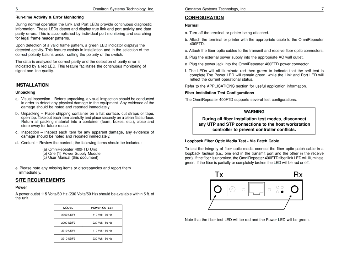
Loopback Fiber Optic Media Test - Via Patch Cable
To test the integrity of fiber optic media connect the fiber optic patch cable in a loopback fashion (i.e., one end in the transmit port and the other in the receive port). If the fiber is unbroken, the OmniRepeater 400FTD fiber link LED will illuminate green. If the fiber is partially or completely broken the LED will be red or off.
Tx |
|
|
|
|
| Rx | ||
|
|
|
|
|
|
|
|
|
|
|
|
|
|
|
|
|
|
|
|
|
|
|
|
|
|
|
|
|
|
|
|
|
|
|
|
|
|
|
|
|
|
|
|
|
|
|
|
|
|
|
|
|
|
|
|
|
|
|
|
|
|
|
|
|
|
|
|
|
|
|
|
Note that the fiber test LED will be red and the Power LED will be green.