8 | Omnitron Systems Technology, Inc. |
Loopback Fiber Optic Media Test - Via Patch Panel
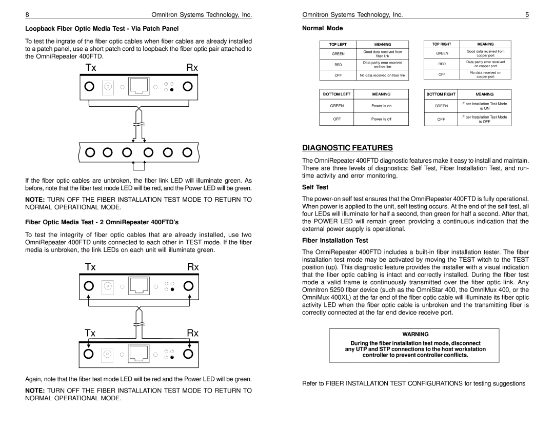
To test the ingrate of the fiber optic cables when fiber cables are already installed to a patch panel, use a short patch cord to loopback the fiber optic pair attached to the OmniRepeater 400FTD.
Tx |
|
|
|
|
|
|
|
|
|
|
|
| Rx | ||
|
|
|
|
|
|
|
|
|
|
|
|
|
|
|
|
|
|
|
|
|
|
|
|
|
|
|
|
|
|
|
|
|
|
|
|
|
|
|
|
|
|
|
|
|
|
|
|
|
|
|
|
|
|
|
|
|
|
|
|
|
|
|
|
|
|
|
|
|
|
|
|
|
|
|
|
|
|
|
|
|
|
|
|
|
|
|
|
|
|
|
|
|
|
|
|
|
|
|
|
|
|
|
|
|
|
|
|
|
|
|
|
|
|
|
|
|
|
|
|
|
|
|
|
|
|
|
|
|
|
|
|
|
|
|
|
|
|
|
|
|
|
|
|
|
|
|
|
|
|
|
|
|
|
|
|
|
|
|
|
|
|
|
|
|
|
|
|
|
|
|
|
|
|
|
|
If the fiber optic cables are unbroken, the fiber link LED will illuminate green. As before, note that the fiber test mode LED will be red, and the Power LED will be green.
NOTE: TURN OFF THE FIBER INSTALLATION TEST MODE TO RETURN TO NORMAL OPERATIONAL MODE.
Fiber Optic Media Test - 2 OmniRepeater 400FTD’s
To test the integrity of fiber optic cables that are already installed, use two OmniRepeater 400FTD units connected to each other in TEST mode. If the fiber media is unbroken, the link LEDs on each unit will illuminate green.
Tx |
|
|
|
|
|
|
|
|
|
| Rx | ||
|
|
|
|
|
|
|
|
|
|
|
|
|
|
|
|
|
|
|
|
|
|
|
|
|
|
|
|
|
|
|
|
|
|
|
|
|
|
|
|
|
|
|
|
|
|
|
|
|
|
|
|
|
|
|
|
|
|
|
|
|
|
|
|
|
|
|
|
|
|
|
|
|
|
|
|
|
|
|
|
|
|
|
|
|
|
|
|
|
|
|
|
|
|
|
|
|
|
Tx |
|
|
|
|
| Rx | |||
|
|
|
|
|
|
|
|
|
|
|
|
|
|
|
|
|
|
|
|
|
|
|
|
|
|
|
|
|
|
|
|
|
|
|
|
|
|
|
|
|
|
|
|
|
|
|
|
|
|
Again, note that the fiber test mode LED will be red and the Power LED will be green.
NOTE: TURN OFF THE FIBER INSTALLATION TEST MODE TO RETURN TO NORMAL OPERATIONAL MODE.
Omnitron Systems Technology, Inc. |
|
|
| 5 | ||||
Normal Mode |
|
|
|
|
|
| ||
|
|
|
|
|
|
|
|
|
| TOP LEFT | MEANING |
| TOP RIGHT | MEANING |
| ||
|
|
|
|
|
|
|
|
|
| GREEN | Good data received from |
| GREEN | Good data received from |
| ||
| fiber link |
| copper port |
| ||||
|
|
|
|
|
|
| ||
|
|
|
|
|
|
| Data parity error received |
|
| RED | Data parity error received |
| RED |
| |||
| on fiber link |
| on copper port |
| ||||
|
|
|
|
|
|
| ||
|
|
|
|
| OFF | No data received on |
| |
| OFF | No data received on fiber link |
|
| ||||
|
| copper port |
| |||||
|
|
|
|
|
|
|
| |
|
|
|
|
|
|
|
|
|
|
|
|
|
|
|
|
|
|
|
|
|
|
|
|
|
|
|
| BOTTOM LEFT |
| MEANING |
| BOTTOM RIGHT |
| MEANING |
|
|
|
|
|
|
|
|
|
|
| GREEN |
| Power is on |
| GREEN |
| Fiber Installation Test Mode |
|
|
|
|
| is ON |
| |||
|
|
|
|
|
|
|
| |
|
|
|
|
|
|
|
|
|
| OFF |
| Power is off |
| OFF |
| Fiber Installation Test Mode |
|
|
|
|
| is OFF |
| |||
|
|
|
|
|
|
|
| |
|
|
|
|
|
|
|
|
|
DIAGNOSTIC FEATURES
The OmniRepeater 400FTD diagnostic features make it easy to install and maintain. There are three levels of diagnostics: Self Test, Fiber Installation Test, and run- time activity and error monitoring.
Self Test
The
Fiber Installation Test
The OmniRepeater 400FTD includes a
WARNING
During the fiber installation test mode, disconnect
any UTP and STP connections to the host workstation
controller to prevent controller conflicts.
Refer to FIBER INSTALLATION TEST CONFIGURATIONS for testing suggestions
