a.
b.
Figure 4. To connect the baseplates, tilt them only slightly, as shown. Do not place them on their side. (a) Use one wrench to hold the hex nut steady (b) while turning the other end of the azimuth axis screw.
6.Place a fender washer (H) onto the azimuth axis screw (I). Then push the screw up through the hole in the ground baseplate (A).Then slide the encoder disk (J), flat side down, onto the azimuth axis screw.
7.Place the brass bushing (F) onto the azimuth axis screw
(I) so that the wide end of the bushing is closest to the encoder disk (J). Seat the bushing onto the encoder disk so that the registration feature on the bushing goes into the hole in the encoder disk. You may need to move the encoder disk around on the azimuth axis screw a bit for the bushing to seat properly.
8.Carefully position the top baseplate (D) over the ground baseplate (A) and lower it so the brass bushing (F) goes into in the center hole of the top baseplate. Place the remaining fender washer (K) onto the shaft of the azimuth axis screw, then thread the hex lock nut (L) onto the end of the azimuth axis screw and tighten it finger tight, for now.
9.To tighten the azimuth axis screw (I) and hex lock nut (L), tilt the assembled Dobsonian base at a slight angle to lift the ground baseplate off the ground. Now, with one wrench (or pliers) hold the head of the azimuth axis screw still while turning the hex lock nut with the other wrench. Figure 4 shows this being done. Tighten the hex lock nut just until the top fender washer is no longer moving freely,
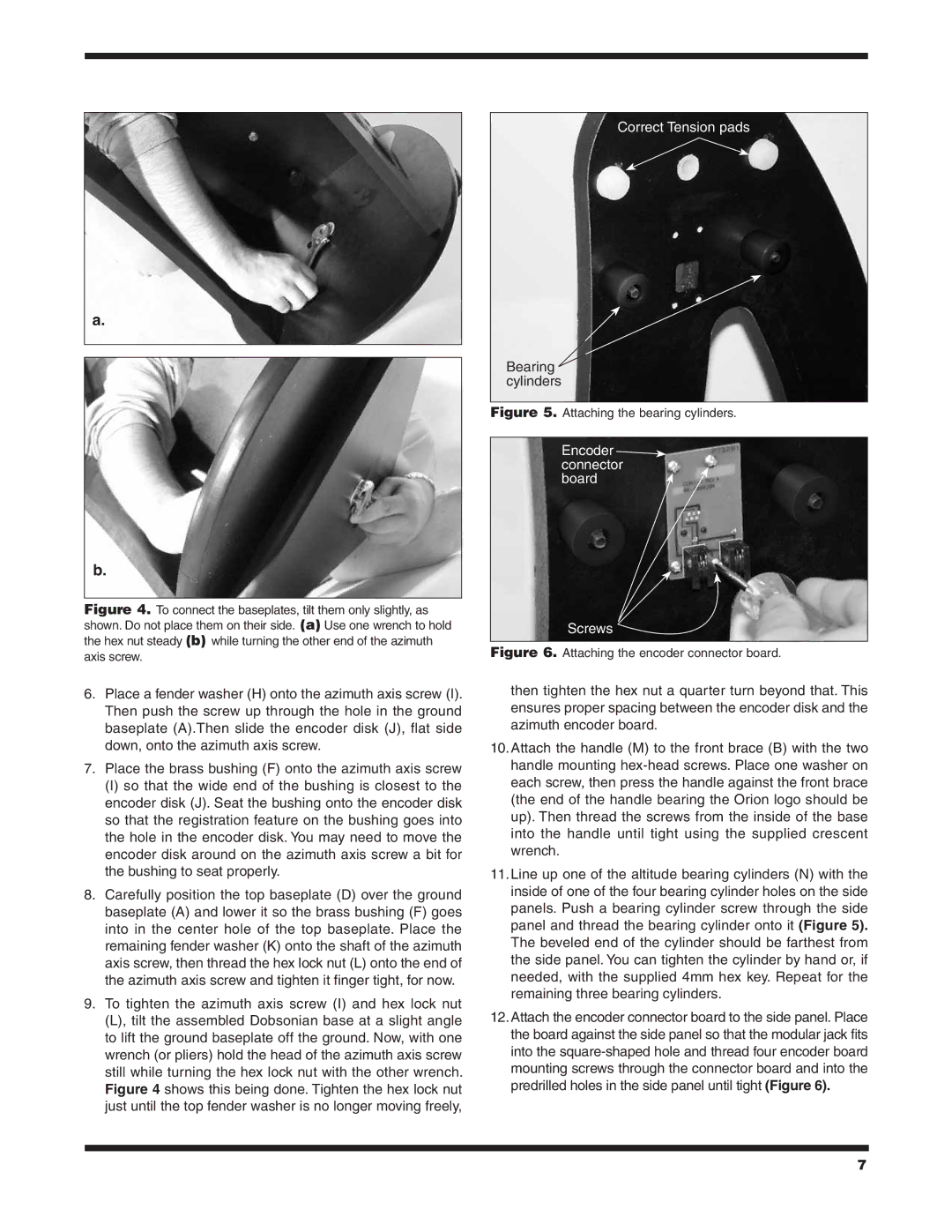
Correct Tension pads
Bearing ![]() cylinders
cylinders
Figure 5. Attaching the bearing cylinders.
Encoder connector board 
Screws
Figure 6. Attaching the encoder connector board.
then tighten the hex nut a quarter turn beyond that. This ensures proper spacing between the encoder disk and the azimuth encoder board.
10.Attach the handle (M) to the front brace (B) with the two handle mounting
11.Line up one of the altitude bearing cylinders (N) with the inside of one of the four bearing cylinder holes on the side panels. Push a bearing cylinder screw through the side panel and thread the bearing cylinder onto it (Figure 5). The beveled end of the cylinder should be farthest from the side panel. You can tighten the cylinder by hand or, if needed, with the supplied 4mm hex key. Repeat for the remaining three bearing cylinders.
12.Attach the encoder connector board to the side panel. Place the board against the side panel so that the modular jack fits into the
7