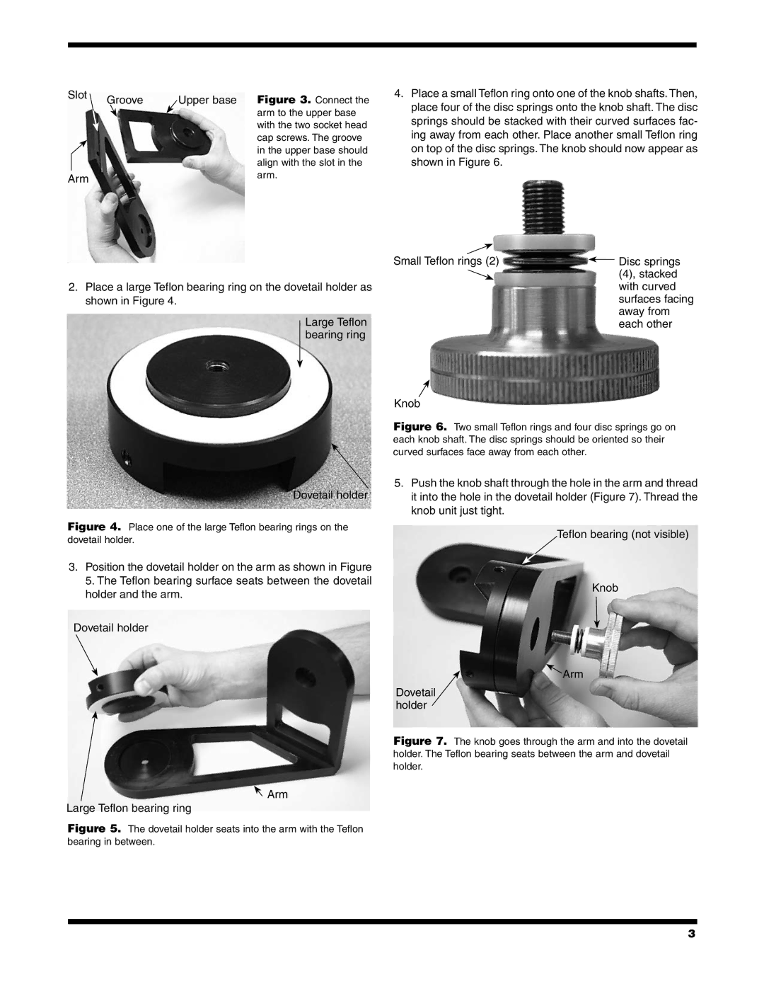
Slot | Groove | Upper base | Figure 3. Connect the |
| |||
|
|
| arm to the upper base |
|
|
| with the two socket head |
|
|
| cap screws. The groove |
|
|
| in the upper base should |
|
|
| align with the slot in the |
Arm |
|
| arm. |
|
|
|
4.Place a small Teflon ring onto one of the knob shafts. Then, place four of the disc springs onto the knob shaft. The disc springs should be stacked with their curved surfaces fac- ing away from each other. Place another small Teflon ring on top of the disc springs. The knob should now appear as shown in Figure 6.
2.Place a large Teflon bearing ring on the dovetail holder as shown in Figure 4.
Large Teflon bearing ring
Dovetail holder
Figure 4. Place one of the large Teflon bearing rings on the dovetail holder.
3.Position the dovetail holder on the arm as shown in Figure 5. The Teflon bearing surface seats between the dovetail holder and the arm.
Dovetail holder
![]() Arm
Arm
Large Teflon bearing ring
Figure 5. The dovetail holder seats into the arm with the Teflon bearing in between.
Small Teflon rings (2) |
| Disc springs |
| ||
|
| (4), stacked |
|
| with curved |
|
| surfaces facing |
|
| away from |
|
| each other |
Knob
Figure 6. Two small Teflon rings and four disc springs go on each knob shaft. The disc springs should be oriented so their curved surfaces face away from each other.
5.Push the knob shaft through the hole in the arm and thread it into the hole in the dovetail holder (Figure 7). Thread the knob unit just tight.
Teflon bearing (not visible)
Knob
![]() Arm
Arm
Dovetail holder
Figure 7. The knob goes through the arm and into the dovetail holder. The Teflon bearing seats between the arm and dovetail holder.
3
