Outback Power Systems GFX1312E, GFX1424E Terminals and Ports, Terminals, Ports, and Features

Models: GFX1448E GFX1424E GFX1312E

1 40
Download 40 pages 41.66 Kb
Page 19
Image 19

Installation

Terminals and Ports

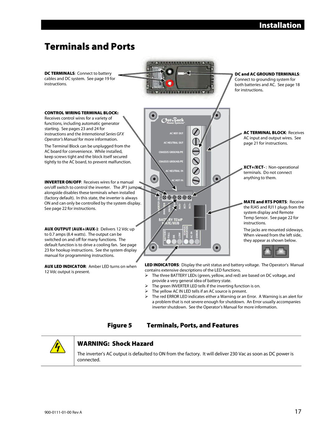
DC TERMINALS: Connect to battery cables and DC system. See page 19 for instructions.

CONTROL WIRING TERMINAL BLOCK: Receives control wires for a variety of functions, including automatic generator starting. See pages 23 and 24 for instructions and the International Series GFX Operator’s Manual for more information.

The Terminal Block can be unplugged from the AC board for convenience. While installed, keep screws tight and the block itself secured tightly to the AC board, to prevent malfunction.

INVERTER ON/OFF: Receives wires for a manual on/off switch to control the inverter. The JP1 jumper alongside disables these terminals when installed (factory default). In this state, the inverter is always ON and can only be controlled by the system display. See page 22 for instructions.

AUX OUTPUT (AUX+/AUX-): Delivers 12 Vdc up to 0.7 amps (8.4 watts). The output can be switched on and off for many functions. The default function is to drive a cooling fan. See page 23 for hookup instructions. See the system display manual for programming instructions.

DC and AC GROUND TERMINALS: Connect to grounding system for both batteries and AC. See page 18 for instructions.

AC TERMINAL BLOCK: Receives AC input and output wires. See page 21 for instructions.

XCT+/XCT- : Non-operational terminals. Do not connect anything to them.

MATE and RTS PORTS: Receive the RJ45 and RJ11 plugs from the system display and Remote Temp Sensor. See page 22 for instructions.

The jacks are mounted sideways. When viewed from the left side, they appear as shown below.

AUX LED INDICATOR: Amber LED turns on when 12 Vdc output is present.

LED INDICATORS: Display the unit status and battery voltage. The Operator’s Manual contains extensive descriptions of the LED functions.

The three BATTERY LEDs (green, yellow, and red) are based on DC voltage, and provide a very general idea of battery state.

The green INVERTER LED tells if the inverting function is on.

The yellow AC IN LED tells if an AC source is present.

The red ERROR LED indicates either a Warning or an Error. A Warning is an alert for a problem that is not severe enough for shutdown. An Error usually accompanies inverter shutdown. See the Operator’s Manual for more information.

Figure 5 Terminals, Ports, and Features

WARNING: Shock Hazard

The inverter’s AC output is defaulted to ON from the factory. It will deliver 230 Vac as soon as DC power is connected.

900-0111-01-00 Rev A

17

Page 19
Image 19
Outback Power Systems GFX1312E, GFX1424E, GFX1448E installation manual Terminals and Ports, Terminals, Ports, and Features

GFX1448E, GFX1424E, GFX1312E specifications

Outback Power Systems has long been recognized for its innovation and reliability in the field of renewable energy solutions, particularly with its GFX series of grid-tied inverters. The GFX1312E, GFX1424E, and GFX1448E models exemplify their commitment to quality and performance, making them ideal choices for both residential and commercial applications.

The GFX1312E is designed to deliver a solid 1300 watts of continuous output power at 12 volts, offering efficient energy conversion for smaller solar setups or off-grid living situations. Its compact design allows for easy installation, while advanced engineering ensures high performance even in challenging conditions. The GFX1312E features a pure sine wave output, which is critical for sensitive electronic devices, ensuring compatibility and safeguarding against potential damage.

Moving up in power capacity, the GFX1424E operates at 1400 watts with a 24-volt configuration. This model is particularly well-suited for medium-sized solar energy systems. It supports 120/240 volts split-phase output, providing greater flexibility for various household appliances and ensuring that users can maximize their energy usage with efficiency. The GFX1424E also incorporates an extensive array of intelligent charging profiles that optimize battery performance and longevity.

The GFX1448E caps the series with impressive 1400 watts of continuous output at 48 volts, catering primarily to larger installations and those requiring more robust energy management solutions. This inverter is equipped with Outback's patented GridZero™ technology, allowing for seamless integration of solar energy production with utility power, helping users to minimize grid dependence while maximizing savings. With advanced features like backup capability and grid-interactive operation, this model is highly versatile.

All three models share key characteristics such as network connectivity through the Outback Power's MATE series of controllers, enabling real-time monitoring and system management. They are designed for durability and have protective features against overloads and short circuits, ensuring reliable performance over time. With their modular design, users can easily scale their system by connecting multiple units, making these inverters a practical choice for expanding energy needs.

In summary, the Outback Power Systems GFX1312E, GFX1424E, and GFX1448E inverters provide top-tier options for those looking to harness solar energy efficiently. Their respective power outputs, advanced technologies, and user-friendly interfaces position them as excellent choices for both residential and commercial energy solutions, underscoring Outback's reputation as a leader in the renewable energy market.