FEATURE DETAILS
WALL
OUTLET
HIGH
CURRENT
OUTLETS
INDUCTORLESS | COMMON MODE |
INPUT FILTER | DOUBLE "L" FILTER |
POWER PROTECTION
CIRCUITRY
NORMAL MODE BALANCED "L" FILTER
NORMAL MODE BALANCED "L" FILTER
SWITCHED
OUTLETS
NORMAL MODE BALANCED "L" FILTER
ALWAYS ON
OUTLETS
NORMAL MODE BALANCED "L" FILTER
FRONT
PANEL
CONVENIENCE
OUTLET
BANK 1 | BANK 2 | BANK 3 | BANK 4 |
FILTERED OUTLET BANKS
HIGH CURRENT OUTLETS | SWITCHED OUTLETS | ALWAYS ON OUTLETS |
R |
|
|
|
| RS232 C |
|
| 12V TR |
|
| IN |
T |
|
|
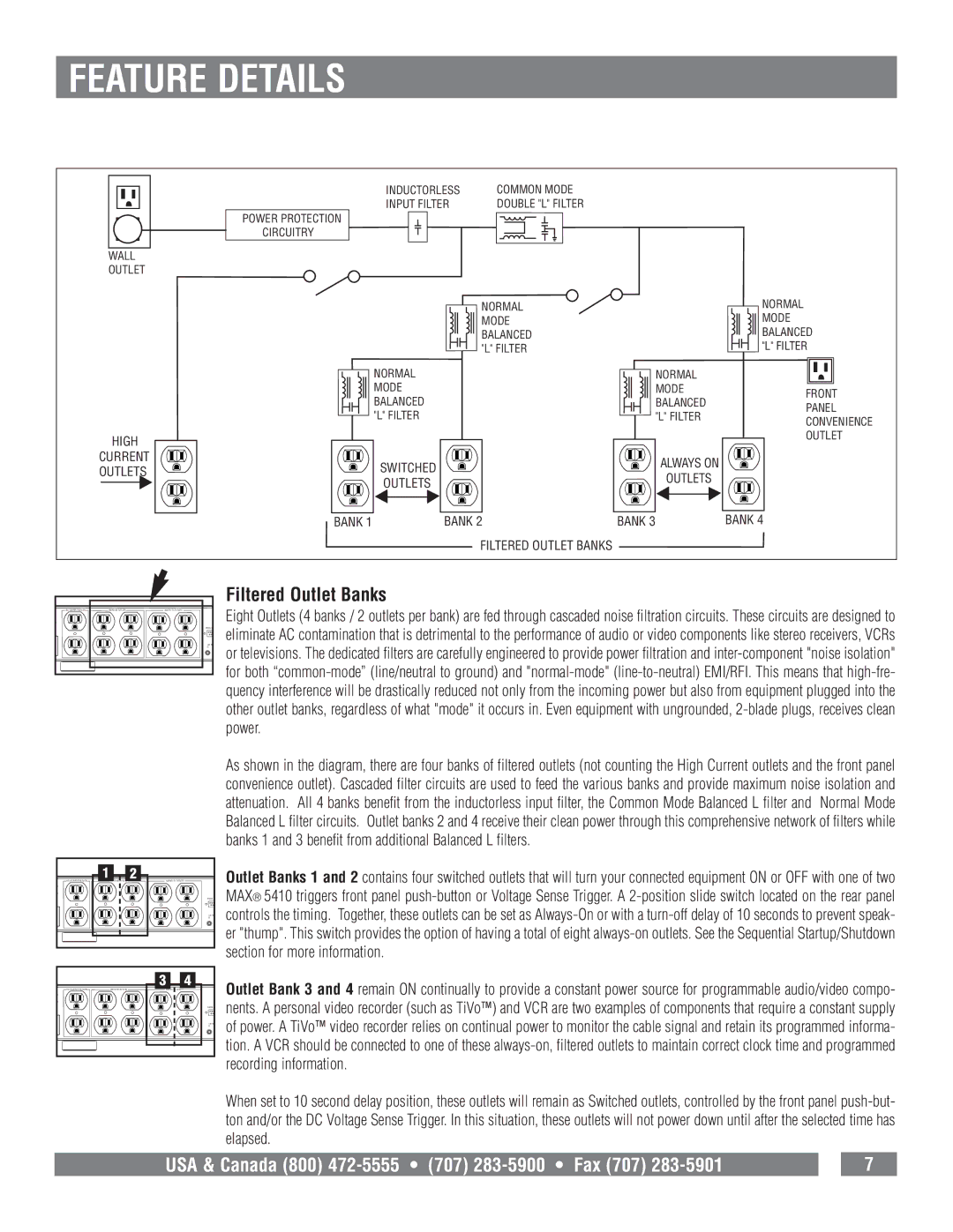
Filtered Outlet Banks
Eight Outlets (4 banks / 2 outlets per bank) are fed through cascaded noise filtration circuits. These circuits are designed to eliminate AC contamination that is detrimental to the performance of audio or video components like stereo receivers, VCRs or televisions. The dedicated filters are carefully engineered to provide power filtration and
HIGH CURRENT OUTLETS | 1SWITCHED OUTLETS | 2 | ALWAYS ON OUTLETS |
ER |
|
|
|
|
|
| RS232 C |
|
|
| 12V TR |
|
|
| IN |
T |
|
|
|
|
| 3 | 4 |
HIGH CURRENT OUTLETS | SWITCHED OUTLETS | ALWAYS ON OUTLETS |
|
ER |
|
|
|
|
|
| RS232 C |
|
|
| 12V TR |
|
|
| IN |
T |
|
|
|
As shown in the diagram, there are four banks of filtered outlets (not counting the High Current outlets and the front panel convenience outlet). Cascaded filter circuits are used to feed the various banks and provide maximum noise isolation and attenuation. All 4 banks benefit from the inductorless input filter, the Common Mode Balanced L filter and Normal Mode Balanced L filter circuits. Outlet banks 2 and 4 receive their clean power through this comprehensive network of filters while banks 1 and 3 benefit from additional Balanced L filters.
Outlet Banks 1 and 2 contains four switched outlets that will turn your connected equipment ON or OFF with one of two MAX® 5410 triggers front panel
Outlet Bank 3 and 4 remain ON continually to provide a constant power source for programmable audio/video compo- nents. A personal video recorder (such as TiVo™) and VCR are two examples of components that require a constant supply of power. A TiVo™ video recorder relies on continual power to monitor the cable signal and retain its programmed informa- tion. A VCR should be connected to one of these
When set to 10 second delay position, these outlets will remain as Switched outlets, controlled by the front panel
USA & Canada (800) |
| 7 |