FEATURE DETAILS
TRIGGER | SWITCHED | GROUND | LIN |
| OUTLETS | OK | FAU |
Front Panel Pushbutton
This button controls the “High-Current” and “Switched” outlets.
Sequential Startup/Shutdown Complex audio/video systems may be susceptible to voltage transients generated inter- nally at
Information on setting the delay times is included in the Filtered Outlet Bank and
1.Press and hold switch > 2 seconds to turn the
2.When button is pressed quickly (<2 sec.) SWITCHED and HIGH CURRENT outlets turn off for 10 seconds then turn back on in a sequence (per delay settings).The purpose is to cycle power to equipment that locks up.
AC |
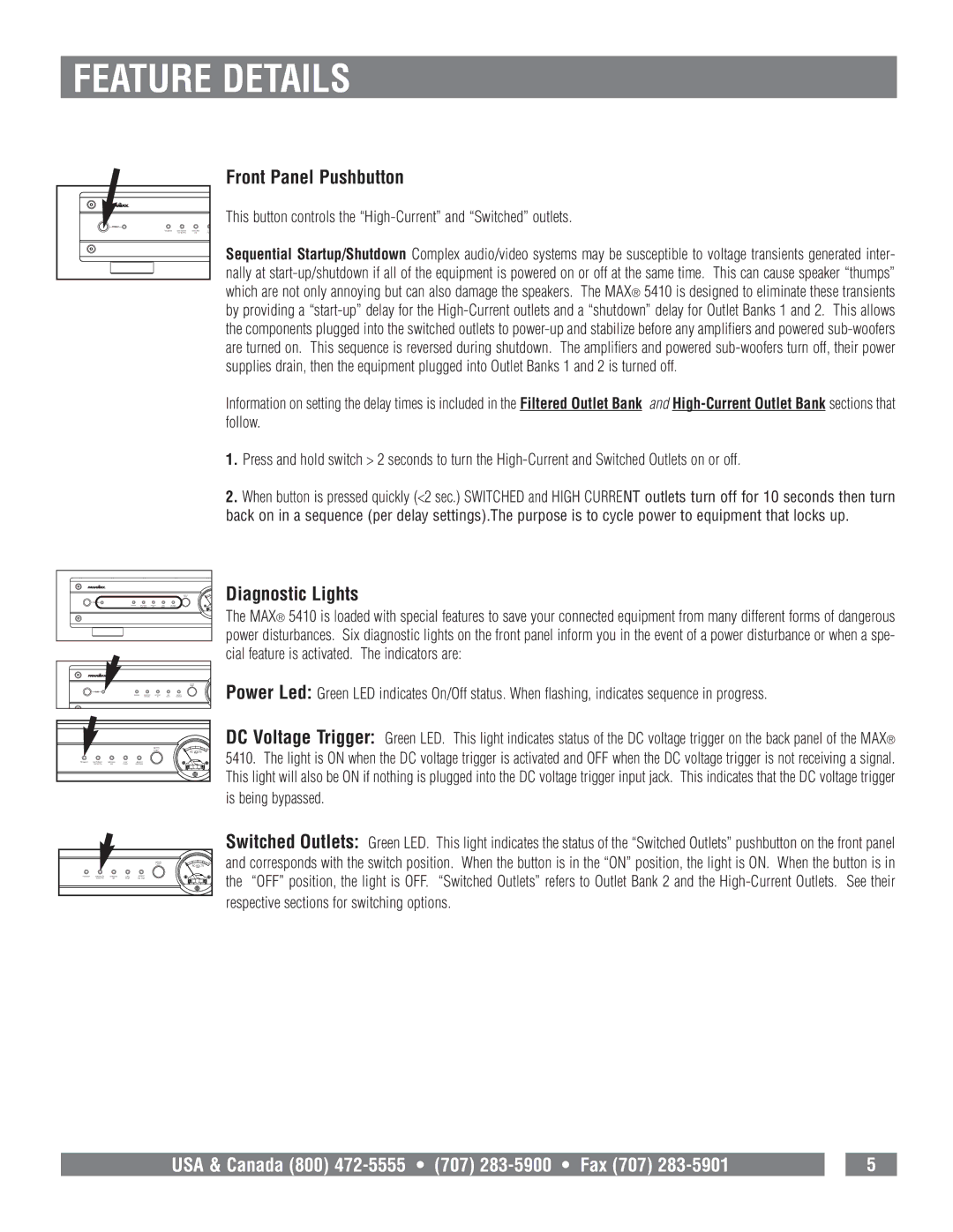
Diagnostic Lights
The MAX® 5410 is loaded with special features to save your connected equipment from many different forms of dangerous power disturbances. Six diagnostic lights on the front panel inform you in the event of a power disturbance or when a spe- cial feature is activated. The indicators are:
METER
LIGHT
TRIGGER | SWITCHED | GROUND | LINE | UNSAFE |
| OUTLETS | OK | FAULT | VOLTAGE |
0
150
AC VOLTS
Power Led: Green LED indicates On/Off status. When flashing, indicates sequence in progress.
DC Voltage Trigger: Green LED. This light indicates status of the DC voltage trigger on the back panel of the MAX® 5410. The light is ON when the DC voltage trigger is activated and OFF when the DC voltage trigger is not receiving a signal. This light will also be ON if nothing is plugged into the DC voltage trigger input jack. This indicates that the DC voltage trigger is being bypassed.
METER
LIGHT
TRIGGER | SWITCHED | GROUND | LINE | UNSAFE |
| OUTLETS | OK | FAULT | VOLTAGE |
0
150
AC VOLTS
Switched Outlets: Green LED. This light indicates the status of the “Switched Outlets” pushbutton on the front panel and corresponds with the switch position. When the button is in the “ON” position, the light is ON. When the button is in the “OFF” position, the light is OFF. “Switched Outlets” refers to Outlet Bank 2 and the
USA & Canada (800) |
| 5 |